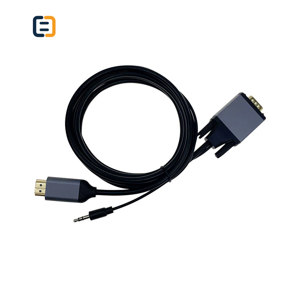
DVI & VGA ConnectivitySC-481-002
HDMI to VGA Adapter With 3.5mm Audio cable - 1080P Full HD
- Input
- HDMI Male
- Output
- VGA Male
Reference MOQ200 pcs
Identify pins, analog or digital behavior, screw fit, conversion electronics and the exact legacy equipment route before quotation.

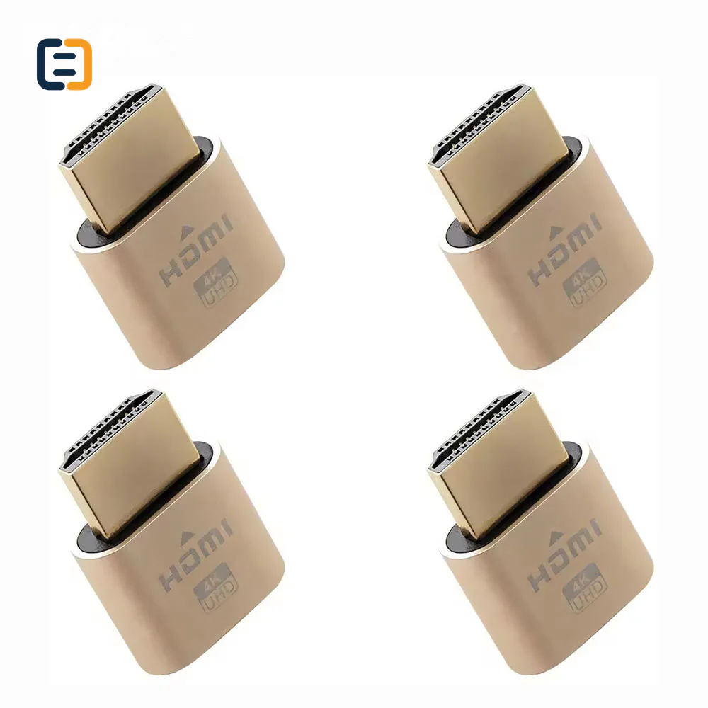
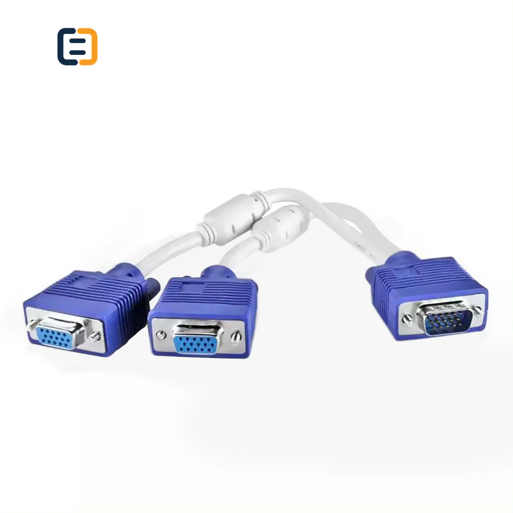
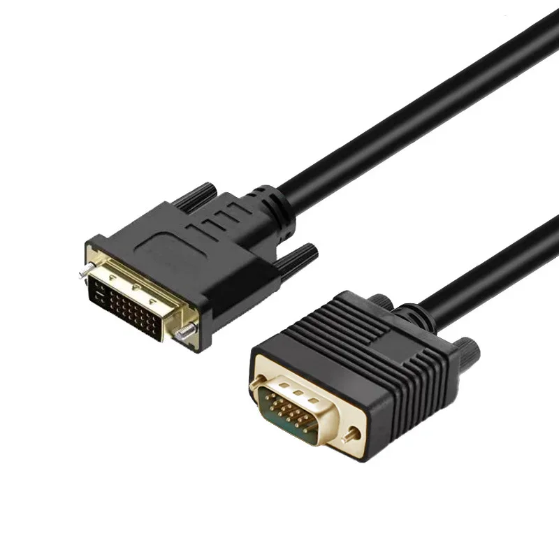
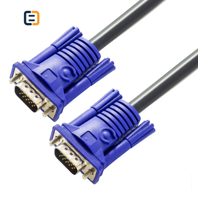
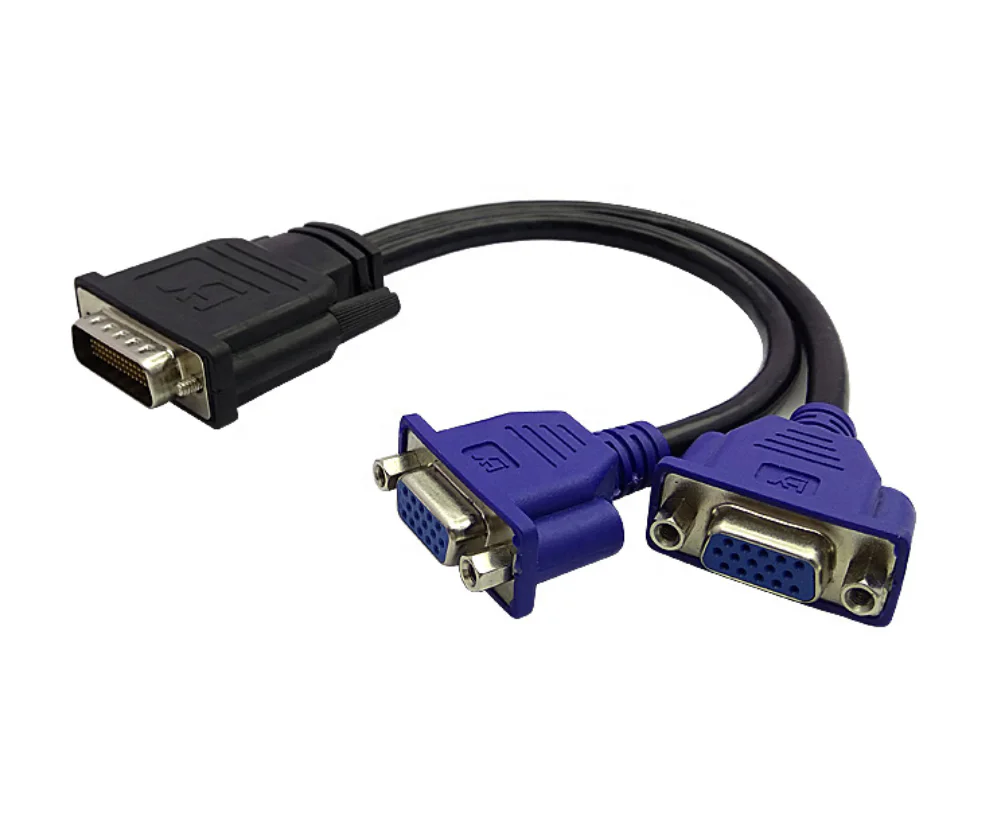
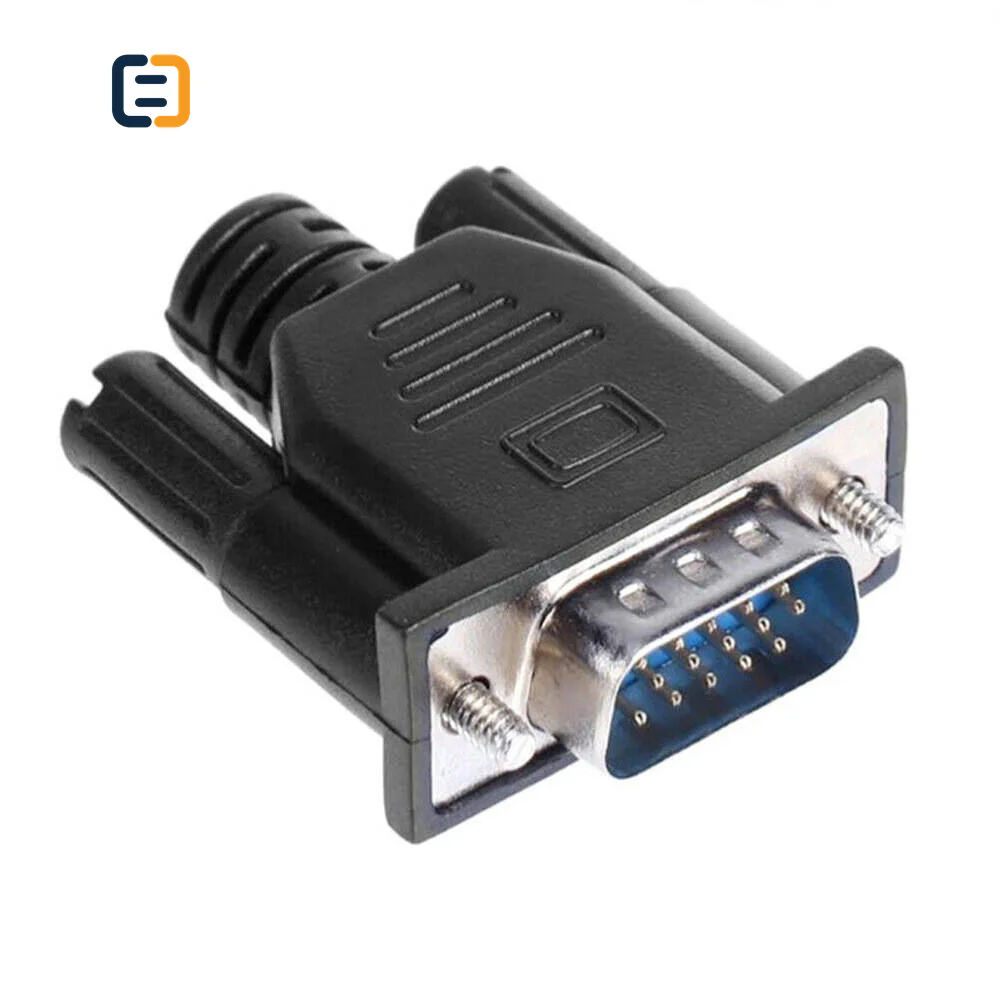
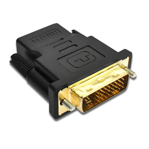
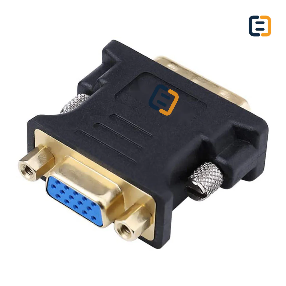
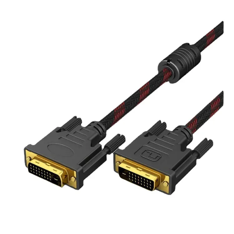
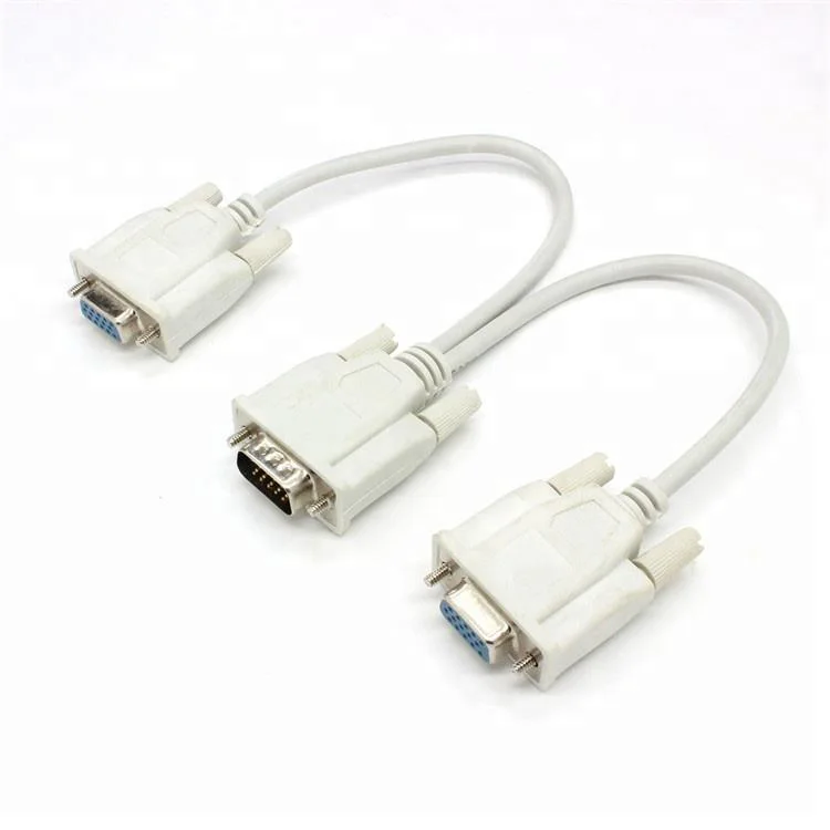
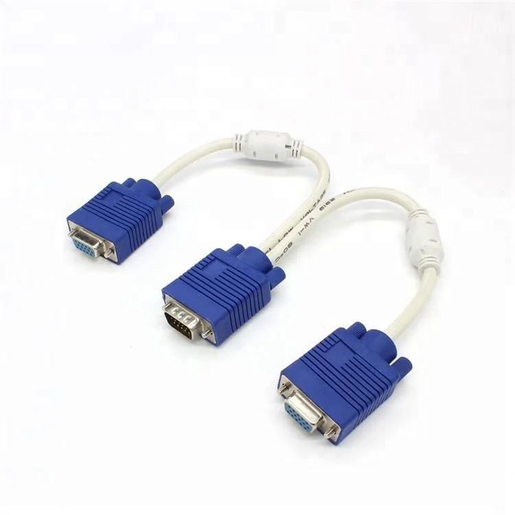
Every listed product remains available as a direct model page even when the visual catalog is paginated.
List the required variation, quantity, destination market and any evidence your buyer needs.
DVI and VGA products require the exact connector variant, pin configuration, signal direction, target resolution and connected equipment. Photos or port drawings are useful when the connector subtype is uncertain.
Use these routes to narrow the catalog. The final configuration is confirmed against the exact application and order.
Confirm DVI-D, DVI-I or other required subtype, link format, pin layout and connector gender.
Filter relevant models02Define analog source and display, route length, screw posts and required resolution behavior.
Filter relevant models03Compare each VGA to HDMI adapter or DVI to HDMI adapter by source-to-display direction, active electronics, power and audio handling.
Filter relevant models04Match video connector, control/peripheral needs and mechanical installation around older systems.
Filter relevant modelsOpen a model page for its listed attributes, images and product-specific RFQ. These cards are starting points, not a claim that one model fits every route.
Legacy display connectors have multiple pin layouts and signal types. A port photo or drawing can prevent an incorrect quotation. These are requirement checks, not unverified claims about every catalog model.
Use the tabs as an RFQ checklist. Listed catalog attributes remain reference data until the exact model and order are confirmed.
DVI and VGA families contain visually similar variants that are not interchangeable.
The connector body does not guarantee that the required signal exists at both ends.
Rack depth, screw access and cable stiffness can decide whether a replacement works.
Document the old and new route so the next replacement does not restart the investigation.
Compatibility statements are meaningful only when tied to the final equipment, route, configuration and quoted model.
Plan model-specific evidenceUse the final application and quoted configuration. Keep the approved sample, result and open exceptions tied to the model and order.
 Packaging and identification planning
A small naming error can make a DVI or VGA replacement unusable. OEM handling should keep pin arrangement, gender, direction and fastening details visible from approval through warehouse picking.
Record subtype, gender, pins and screw geometry.
Set length, flexibility, ferrite and strain relief.
Label active conversion from source to receiver.
Use model and equipment-reference labels for replacement stock.
Final feasibility, MOQ, lead time and document availability are confirmed for the exact quotation.

One complete requirement brief gives engineering, purchasing and the supplier the same decisions to review.
Build a Requirement BriefUse these application planning scenarios to identify the equipment and acceptance conditions that belong in your RFQ.
Match legacy ports, cabinet space and fixed replacement procedures.
Confirm source signal, display input and active conversion where needed.
Validate video plus control peripherals and cable reach as one route.
Label connector subtype, gender and supported equipment clearly for field replacement.
Certificate, report, drawing and catalog availability is checked by exact model, destination and order. These links are planning resources, not substitute evidence.
CoreCavo is operated by WUHAN SUNFULL. The public catalog organizes buyer requirements and model references; final specifications, commercial terms and applicable documents are confirmed through the exact quotation.
Map the DVI / VGA interface, equipment, quantity and destination before selecting a route.
Separate listed attributes from compatibility, construction and document questions that need confirmation.
Use the quoted configuration, record results and retain open exceptions against the approved model.
Keep product code, labels, packaging and change-control requirements aligned through fulfillment.
Start with the equipment manual, a clear straight-on port photo and, where possible, a connector drawing. Record DVI subtype, pin arrangement, gender and screw posts. For VGA, confirm the HD15-style connection and any special cable or breakout arrangement. Avoid classifying the product from a partial image or a familiar shell. One missing or extra pin can distinguish an analog-capable route from a digital-only route, so the evidence attached to the RFQ matters more than a shorthand label.
A connector can expose analog, digital or both depending on subtype and equipment. State the source device and receiving display, then confirm what signal each actually supports. Passive adapters only work when compatible signals are already present; they do not create a missing signal. If conversion is required, specify an active product and its direction. This step prevents a common mistake: buying a mechanically mating adapter for two ports that cannot communicate electrically without conversion electronics.
For HDMI, DisplayPort, USB-C, DVI and VGA combinations, name the sending port first and the receiving port second. Add power and audio needs. Analog conversion can introduce image-quality, timing and scaling limits, while some digital routes depend on source capability. Test with the intended equipment rather than a generic laptop and monitor. Put direction on the package and product label because the same connector pair may exist in a reverse product with different electronics.
State resolution, refresh rate and any tolerance for analog image adjustment. VGA quality can be affected by cable length, shielding, source output and display input. DVI digital routes have their own link and timing limits. If the equipment uses a nonstandard or fixed timing, provide that information early. Sample approval should include cold start and reconnect behavior, not only a brief static image, because older equipment may negotiate or detect displays differently after power cycles.
Legacy connectors often use screws and bulky shells. Measure access around the port, post spacing, available depth and the bend required immediately after the connector. Ferrite cores can interfere with tight cabinet routes even when they help the intended cable design. For fixed machinery, inspect door clearance and service removal. Approve the exact shell and cable flexibility, then require disclosure if those mechanical parts change; a later substitution can turn a technically correct replacement into an installation problem.
Field technicians benefit from a cable code that maps to known equipment rather than a generic ‘DVI cable’ bin. Labels can state connector subtype, gender, length, direction for active products and an internal equipment reference. Packaging should protect pins and keep adapters with their required power or audio leads. For mixed maintenance kits, use separate inner packs and a packing list. This reduces trial-and-error connections and damage to fragile or difficult-to-replace legacy ports.
Record the old connection, proposed product code, source and display models, port photos, required timing, cable length and sample result. Inspect pins, screws, shell fit, image stability and reconnect behavior. For active converters, include power and audio. Keep the approved sample or detailed photographs with the result sheet. If the equipment is rare, consider approving a small service quantity before the original installation becomes unavailable for later comparison.
If any pin or signal detail is unknown, mark it as an open question rather than forcing a confident product name. Send photos and drawings, quantity, forecast, equipment references, direction, mode, length, mechanical limits, packaging and document needs. Ask suppliers to state assumptions and alternatives. A quotation that exposes uncertainty is safer than a low price based on the wrong subtype, and it gives engineering a focused list of checks for the first sample.
Legacy components can become unavailable with little notice, so decide what makes a replacement equivalent. Connector pins, gender, signal direction, active chipset function, power, supported timing, shell dimensions and screw geometry may all matter. Require a proposed substitute to be identified before shipment and compare it with the retained approval record. This protects service continuity without pretending that any cable with the same visible ends is a drop-in replacement.
Use these procurement priorities to compare the proposed model, approval conditions and repeat-order requirements.
Buyers need pin layout, gender and equipment reference because visually similar DVI variants can carry different signals.
VGA and DVI-I/DVI-D decisions should be based on the signal exposed by the equipment, not the connector shell alone.
Screw posts, ferrites, shell depth and cable bend must fit older cabinets and tightly packed ports.
Replacement stock should be labeled by cable code and applicable equipment so technicians do not test several near-identical variants on site.
Answers separate catalog references from decisions that require an exact route, model and RFQ.
Provide a clear front view of both ports, the equipment models, connector gender, pin arrangement and screw details. State whether the route is expected to carry analog or digital video and the required resolution. DVI-D, DVI-I and other layouts can look similar in casual photos, so an equipment manual or drawing is valuable.
A passive adapter cannot create a signal type that the source does not provide. Analog-to-digital or digital-to-analog routes normally require active conversion in a defined direction and may need power. Name the source and receiving devices, required mode and audio needs, then approve the converter with that equipment pair.
The electronics are designed to accept one source signal and produce another receiving format. The same connector pair can therefore represent two different one-way products. State the route from sending device to display, and place direction on labels and instructions. Mechanical mating does not prove reverse operation.
Check connector-shell width and depth, screw posts, access for tightening, ferrite location, cable flexibility and bend near the port. Older cabinets and KVM panels can have limited space. Approve the actual sample in the installation, because a shell change can affect fit even when pins and electrical description remain unchanged.
Use the installed route length and required timing, then test image stability and quality with the intended source and display. Analog performance can depend on construction, shielding, equipment and routing. A short sample should not automatically approve a much longer SKU. Record the tested length and any acceptable adjustment or limitation.
Yes. A service kit can group approved cable codes, active adapters, power leads and instructions, provided each variant remains clearly identified. Labels should include connector subtype, gender, length, direction where relevant and an internal equipment reference. Final pack-out, quantity and MOQ are confirmed after the replacement list is reviewed.
Keep the product code, port photos or drawing, equipment references, cable length, required timing, sample result and packaging label. An approved sample is useful when practical. This evidence makes later replacement and supplier-change review faster and reduces the risk of relying on an incomplete description written years earlier.
Move from product comparison to compatibility, custom construction and required documents without restarting the sourcing process.
Include model codes where known, or describe the interface, equipment, length, quantity, destination, packaging and evidence requirements.