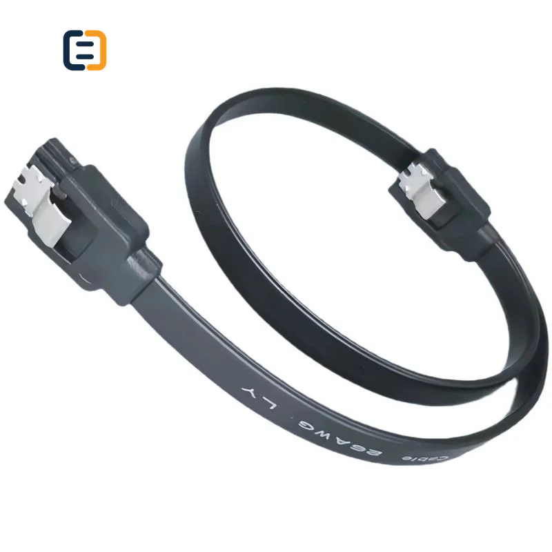
Data & Storage CablesSC-HS-011
SATA 3.0 Cable - 6 Gigabits Per Second
- Data Transfer Rate
- 6 Gigabits Per Second
- Color
- Transparent Blue
Reference MOQ200 pcs
Define host and device interfaces, latch, connector angle, route length, clearance and assembly requirements for OEM or integration sourcing.

Every listed product remains available as a direct model page even when the visual catalog is paginated.
List the required variation, quantity, destination market and any evidence your buyer needs.
Data and storage cable selection starts with the exact host and device interfaces, protocol generation, connector orientation, route length and enclosure constraints. Send a port photo, drawing or existing model reference when available.
Use these routes to narrow the catalog. The final configuration is confirmed against the exact application and order.
Confirm interface generation, straight or angled connectors, latch requirement and internal route length.
Filter relevant models02Use equipment drawings to define cable exit direction, bend, clearance and service access.
Filter relevant models03Match connector, latch, length and equipment reference to reduce field-selection errors.
Filter relevant models04Provide pinout, drawing, BOM or approved sample when the route extends beyond a standard SATA cable.
Filter relevant modelsOpen a model page for its listed attributes, images and product-specific RFQ. These cards are starting points, not a claim that one model fits every route.
Internal data and storage cables should be selected around the enclosure, port orientation and protocol route rather than appearance alone. These are requirement checks, not unverified claims about every catalog model.
Use the tabs as an RFQ checklist. Listed catalog attributes remain reference data until the exact model and order are confirmed.
Identify the controller and device interfaces and any equipment-specific keying or pinout.
Connector angle and cable exit should be shown relative to the equipment, not named in isolation.
Retention must balance vibration risk with service access and connector compatibility.
Approve the cable inside the real or representative enclosure with normal assembly steps.
Compatibility statements are meaningful only when tied to the final equipment, route, configuration and quoted model.
Plan model-specific evidenceUse the final application and quoted configuration. Keep the approved sample, result and open exceptions tied to the model and order.
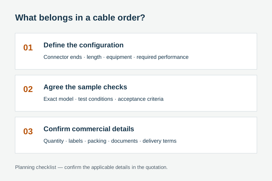 Packaging and identification planning
For integration programs, connector orientation, length and label are production-control details. The approved drawing and equipment reference should remain linked to the cable code through repeat orders.
Fix straight or angled exit with an equipment-view drawing.
Define latch and service-release requirements.
Set length, ties, sleeve and abrasion protection.
Use model, drawing revision, barcode and pack quantity.
Final feasibility, MOQ, lead time and document availability are confirmed for the exact quotation.

One complete requirement brief gives engineering, purchasing and the supplier the same decisions to review.
Build a Requirement BriefUse these application planning scenarios to identify the equipment and acceptance conditions that belong in your RFQ.
Match controller, drive-cage geometry, airflow and service access.
Control connector angle, route length, latches and repeated assembly.
Use drawings, retention and routing controls around fixed equipment.
Label the approved cable by equipment reference and installation orientation.
Certificate, report, drawing and catalog availability is checked by exact model, destination and order. These links are planning resources, not substitute evidence.
CoreCavo is operated by WUHAN SUNFULL. The public catalog organizes buyer requirements and model references; final specifications, commercial terms and applicable documents are confirmed through the exact quotation.
Map the Data / Storage interface, equipment, quantity and destination before selecting a route.
Separate listed attributes from compatibility, construction and document questions that need confirmation.
Use the quoted configuration, record results and retain open exceptions against the approved model.
Keep product code, labels, packaging and change-control requirements aligned through fulfillment.
Name the controller, motherboard or backplane side and the drive or device side. Confirm connector type, keying and required protocol generation. If the route is equipment-specific, include the host and device models or a drawing. A familiar SATA-style connector may still sit in a special mechanical arrangement, so interface identification should be connected to the actual assembly rather than selected from an isolated product photo.
Terms such as left-angle and right-angle can reverse when the connector is viewed from the cable side, device side or board side. Use a photograph or simple drawing that shows the installed equipment, keyed connector and desired cable exit. Mark up, down, left or right relative to a stable feature. Approve the sample in that orientation. This small step prevents an otherwise correct cable from colliding with a cover, drive cage or neighboring port.
Trace the cable around intended bends and tie points, then include enough service movement without leaving excess cable that blocks airflow or contacts a fan. State finished length and tolerance. If several enclosure sizes use the same assembly, decide whether one length is genuinely suitable or separate SKUs are cleaner. A bench-measured straight distance is rarely a complete route. Review how the cable is installed and removed so length supports both production assembly and service.
Latching connectors can resist accidental disconnects, but the equipment port must support them and service staff need access to release them. In tight spaces, a latch can be difficult to reach; in vibration-prone equipment, no latch may be unacceptable. State the required retention method, insertion orientation and pull direction. Check whether cable ties or clips add strain near the connector. Approval should include assembly and removal, not only a successful initial connection.
Keep data cables away from fan blades, sharp edges and unnecessary heat. Define sleeve, abrasion protection or tie points where needed without crushing or overbending the cable. For high-density enclosures, consider how bundles affect airflow and service access. Electrical performance should be checked with representative device operation and transfer, but routing quality remains a mechanical production issue. Photos of the approved route can be more useful to assemblers than a paragraph in the BOM.
Install the cable with all covers, drives, fans and neighboring assemblies present. Check connector engagement, latch action, bend, clearance and device detection. Run a representative data workload, then remove and reinstall the serviced component once if that reflects normal maintenance. Record the cable code, length and drawing revision. A sample that works only with the enclosure open has not proven the final assembly condition.
Use a cable code linked to connector drawings, length, latch, jacket or sleeve and label. Keep an approved sample or detailed inspection images. If a supplier changes connector tooling, cable construction or length tolerance, require disclosure and decide what must be rechecked. Label inner packs with the BOM code and quantity. This allows incoming inspection and production staff to detect a substitution before it reaches the assembly line.
Provide host and device interfaces, protocol, equipment model, orientation drawing, route length, tolerance, latch, cable exit, tie or sleeve needs, quantity, forecast, label, pack quantity and acceptance method. Mark any open dimension clearly. If a sample or old cable is supplied as a reference, identify which features must be copied and which can change. The resulting quotation can separate standard components from custom tooling or assembly work and reduce avoidable fit iterations.
After the pilot build, capture whether installers had difficulty reaching the latch, routing the bend, reading the label or closing the enclosure. Confirmed assembly observations can improve the drawing, work instruction or next cable revision. Keep them separate from unverified assumptions about electrical performance. This gives the buyer a practical improvement path and helps the supplier understand which mechanical details have production impact even when the interface specification remains unchanged.
Use these procurement priorities to compare the proposed model, approval conditions and repeat-order requirements.
Buyers need connector exit direction tied to the equipment view because left and right become ambiguous when viewed from opposite sides.
A cable must clear covers, fans, drive cages and neighboring ports after final routing, not only connect on an open bench.
Cable code, drawing revision, length, latch and pack quantity should remain stable across integration orders.
Retention and tie points should prevent accidental disconnects without making drive replacement or troubleshooting unnecessarily difficult.
Answers separate catalog references from decisions that require an exact route, model and RFQ.
Provide host and device interfaces, required protocol generation, connector orientation, latch requirement, finished length and tolerance, equipment model or enclosure drawing, quantity, label and pack-out. Add routing, tie, sleeve and clearance constraints. A photo showing the installed connector view is especially useful for angled designs.
Direction changes with the viewing side. A supplier and buyer may use opposite conventions while describing the same shell. Show the keyed connector and desired cable exit on an equipment-view drawing or marked photo, then approve the sample in the enclosure. Visual orientation is more reliable than a direction word alone.
It depends on port compatibility, vibration, accidental-pull risk and service access. A latch can improve retention but may be hard to release in a tight drive cage. State the assembly and maintenance need, then test insertion and removal in the final enclosure. Do not assume every mating port supports the same latch geometry.
Follow the actual routed path around bends and tie points, adding enough service movement while avoiding excess that blocks airflow or contacts fans. State a finished-length tolerance. Test with covers and neighboring parts installed. Straight-line distance on an open bench can miss both clearance and service requirements.
Install it in representative equipment, verify connector engagement, latch and cover clearance, then run device detection and a representative transfer. Review routing, abrasion points, airflow and service removal. Record the cable code, drawing revision, length and pack label so repeat orders have a stable inspection reference.
Often the base interface is standard, while angle, length, latch, sleeve, tie points and labeling require review. Provide an equipment drawing or reference sample. Final feasibility, MOQ and lead time depend on whether existing components fit or new tooling or assembly work is needed.
Use a unique cable code linked to equipment reference, connector orientation, length and latch. Put the same code and quantity on inner packs and the BOM. Where several near-identical variants exist, add a small orientation image or color-independent mark rather than relying only on a handwritten description.
Move from product comparison to compatibility, custom construction and required documents without restarting the sourcing process.
Include model codes where known, or describe the interface, equipment, length, quantity, destination, packaging and evidence requirements.