Choosing a conductor is not a lookup exercise in which one AWG number produces one safe current. A cable assembly operates as part of a circuit: a source with tolerances feeds a load that may change by operating state, through outgoing conductors, terminations, contacts and a return path. Every resistive element consumes voltage and produces heat. Ambient temperature, bundling, duty cycle, insulation, connector limits and the governing equipment standard determine whether the result is acceptable.
For a buyer, the useful starting point is an end-to-end electrical budget, not an internet ampacity chart. Define the voltage that the equipment must receive at its worst credible load, subtract source and interface allowances, and allocate the remaining loss across the complete cable path. AWG can then help identify candidate conductor constructions. The finished assembly still needs measurements under controlled conditions.
This guide concerns engineering and procurement of low-voltage cable assemblies. It is not a wiring-code interpretation, approval for mains or high-energy work, or a do-it-yourself modification procedure. Energized testing and work on hazardous circuits must be planned and performed by qualified people using applicable standards, rated equipment and formal safety controls. OSHA’s rules, for example, restrict testing work to qualified persons and require suitable instruments; local obligations may differ and must be established for the project.
The four numbers buyers often collapse into one
An RFQ may say “18 AWG, 5 A, two metres.” That line contains useful clues, but it does not establish performance. Separate four concepts before making a decision.
AWG designator. American Wire Gauge identifies a nominal conductor size system. It does not define conductor material, plating, stranding, finished-cable resistance, insulation temperature rating, connector capability or permissible temperature rise. A stranded conductor with the same nominal designator as a solid reference wire can have a different measured resistance because of strand geometry, lay, material and processing.
Conductor resistance. Resistance is the value used in a voltage-drop calculation. It changes with conductor material, actual cross-sectional area, length and temperature. Terminations and contacts add resistance that an AWG table does not include. Buyers should distinguish a reference value from a controlled finished-product requirement.
Current profile. The load may have steady, startup, inrush, pulse, sleep and fault states. A short peak can matter to device brownout even if it does not establish the same thermal state as continuous current. “Maximum current” should identify magnitude, duration, repetition and simultaneous loads.
Allowable temperature and voltage performance. A system may fail its voltage requirement long before a conductor reaches an insulation temperature limit. Conversely, a voltage-drop calculation alone does not prove acceptable conductor, contact or bundle temperature. Electrical and thermal criteria are separate gates.
IEC 60228 provides internationally used nominal conductor areas and resistance values for conductors in insulated cables. Its existence does not make every finished assembly compliant, nor replace the product, connector or installation standard. NIST’s Copper Wire Tables provide traceable copper-wire relationships at stated reference conditions. Use such documents to anchor calculations, then control the actual construction and test condition.
Build the budget from the load backward
Start at the equipment input because insufficient voltage causes the functional problem there. A practical budget has at least six rows:
| Budget item | Buyer-controlled question | Evidence expected |
|---|---|---|
| Load requirement | What minimum voltage is required at each operating state? | Equipment specification or measured, approved load envelope |
| Source output | What is the minimum source voltage at relevant current and temperature? | Source specification and, when necessary, system measurement |
| Outgoing conductors | What is their maximum resistance at the controlled reference condition? | Construction drawing plus resistance requirement |
| Return conductors | Is the return identical, shared or routed differently? | Circuit diagram and conductor schedule |
| Contacts and terminations | How many interfaces are in series, and what limits apply after conditioning? | Connector data, termination specification and measured records |
| Reserved margin | What remains for aging, variation and unmodelled effects? | Documented engineering allocation, not an accidental remainder |
The source-to-load relationship can be expressed as:
V_load = V_source − I × R_total_path
For a simple two-conductor DC lead, R_total_path includes both outgoing and return conductor lengths plus every termination and contact in series. If quoted length is one way, the conductor loop is approximately twice that length before connector and shared-return effects are added. Calculations based on one-way length alone often understate loss.
The resistive heating represented by the same simplified model is:
P_loss = I² × R_total_path
These equations are bookkeeping tools, not a full safety model. They do not by themselves cover current sharing, intermittent loads, thermal coupling, skin/proximity effects at frequency, insulation behavior, fault energy, arc risk, electromagnetic performance or requirements of a particular interface.
A worked low-voltage example, with deliberate limits
The following is a hypothetical engineering example, not a CoreCavo product claim, current rating or build instruction.
A 24 V device draws 2.0 A continuously. The cable is 3 m one way, so a simple two-conductor path contains 6 m of power conductor. For an early estimate, an engineer uses approximately 20.95 Ω/km at 20 °C for annealed copper corresponding to an 18 AWG reference value.
- Loop resistance estimate:
20.95 Ω/km × 0.006 km = 0.1257 Ω. - Conductor voltage-drop estimate:
2.0 A × 0.1257 Ω = 0.2514 V. - Conductor loss estimate:
2.0² × 0.1257 Ω = 0.5028 Wacross the loop. - Estimated load voltage from nominal 24.0 V, before other losses:
23.7486 V.
That arithmetic is not an acceptance result. It omits source tolerance, contact resistance, termination variation and temperature. If copper operates 30 °C above the 20 °C reference and an engineering estimate uses a coefficient near 0.00393 per °C, resistance would be roughly 11.8% higher. Predicted conductor-only drop would rise to about 0.281 V. The exact design must use the controlled conductor construction and appropriate reference values, then measure the finished path.
The example says nothing about whether 18 AWG is thermally acceptable in a particular jacket, bundle, enclosure or standard. It demonstrates only how a resistance budget exposes assumptions.
Why low-voltage systems can be especially sensitive
A one-volt loss consumes a small percentage of a 48 V budget but a large percentage of a 5 V budget. A cable that feels electrically “heavy enough” can still cause resets, failed negotiation or reduced downstream power when source, connector and cable tolerances accumulate.
Consider a second hypothetical screening example. A team examines a 5 V, 3 A load over a 2 m one-way lead. Using an illustrative 24 AWG copper reference resistance near 84.22 Ω/km gives a 4 m loop estimate of about 0.337 Ω and a conductor-only drop of about 1.01 V at 3 A. The conclusion is not “use a particular AWG.” The conclusion is that this proposed architecture cannot be accepted from nominal labels: the team must revisit source voltage, allowable load voltage, length, conductor allocation, connector system, interface rules and actual resistance.
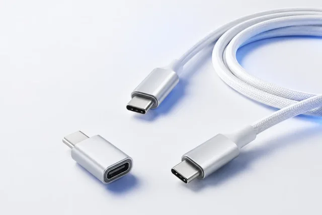
This is intentionally not presented as a USB design. USB Type-C and USB Power Delivery operate within interface-specific cable, connector, identification, negotiation and compliance requirements maintained by USB-IF. A generic Ohm’s-law calculation cannot establish that a cable is USB compliant, supports a particular power level or may use a particular marking. The current released USB-IF specification set and compliance requirements must be used for an actual USB design.
Add every series interface to the ledger
A detachable power path may contain a PCB trace, board connector, receptacle contact, plug contact, crimp or solder termination at each end, inline fuse or switch, and shared return. Each contributes loss. Some contributions are small when new, but the engineering question is the maximum acceptable value after defined conditioning and manufacturing variation.
Create a resistance ledger with separate allocations:
| Path element | Quantity in series | Initial estimate | Maximum requirement | Verification stage |
|---|---|---|---|---|
| Positive conductor | 1 path | Project input | Drawing-controlled | Incoming/finished test |
| Return conductor | 1 or more | Project input | Drawing-controlled | Incoming/finished test |
| Crimp or solder terminations | Actual count | Component/process input | Project-controlled | Process validation |
| Mated contact pairs | Actual count | Connector input | Project-controlled | Initial and conditioned test |
| Shared/common segment | As designed | System input | System-controlled | System test |
| Measurement leads/fixtures | N/A | Characterized separately | Corrected or bounded | Test-method control |
Do not silently assign a connector’s headline current to the complete assembly. Connector performance depends on contact size, simultaneously loaded positions, ambient conditions, wire size, housing, termination and derating method. Use the exact connector application specification and applicable product standard.
Four-wire resistance measurement can reduce lead-resistance error when low resistances are characterized, but fixture, test current, stabilization time, contact state and temperature still need definition. “Continuity passed” is not enough when the budget depends on milliohms.
Convert the load description into a time profile
Cable loss varies with current, and heat generation varies with current squared. Buyers should provide more than an average.
| State | Current | Duration | Repetition | Minimum load voltage | Concurrent circuits |
|---|---|---|---|---|---|
| Off/sleep | Buyer input | Buyer input | Buyer input | Buyer input | Buyer input |
| Startup/inrush | Buyer input | Buyer input | Buyer input | Buyer input | Buyer input |
| Normal steady operation | Buyer input | Buyer input | Buyer input | Buyer input | Buyer input |
| Peak functional load | Buyer input | Buyer input | Buyer input | Buyer input | Buyer input |
| Abnormal/fault case | Safety-design input | Safety-design input | Safety-design input | Not a normal-use criterion | Protection-dependent |
This separates functional voltage-drop work from protection and safety analysis. A fuse, current limiter or source-protection feature must be selected and validated within equipment design; a thicker conductor is not a fault strategy. A short peak should not become a continuous cable rating without a justified thermal model and applicable standard.
Temperature changes resistance and allowable operation
Copper resistance increases with temperature. A first-order correction may help early budgeting, but actual cable temperature results from conductor loss, contact loss, ambient, enclosure, bundling, neighboring circuits, duty cycle, jacket/insulation construction and heat paths.
This creates an iterative loop:
- estimate path resistance at a defined reference temperature;
- predict drop and losses at each load state;
- define the worst credible environment and installation;
- build the exact assembly with controlled components;
- measure end-to-end drop and temperatures at defined locations;
- compare results with equipment, component and product-standard limits;
- revise the model and margins using measured evidence.
Avoid “rated to 80 °C, therefore acceptable.” A material temperature marking, when valid for an exact construction and use, is not permission to operate every contact, enclosure surface or neighboring component at that temperature. Connector, touch-temperature or equipment requirements may be lower. Local hot spots can be hidden by an average cable-surface reading.
Instrumentation affects results. Specify sensor type and attachment, resistance method, load accuracy, source measurement point, ambient measurement, stabilization criterion, airflow, cable arrangement and recording interval. A coiled cable on an insulating bench is not equivalent to the installed route unless the project defines it so.
Treat length as an electrical configuration item
Length changes voltage margin, signal performance, mechanical routing, flex exposure and packaging. A family sold in several lengths should not inherit one claim automatically.
Record finished length and tolerance; measurement datums; one-way versus loop length; conductor routing inside molded ends; parallel conductors and current-sharing controls; shared returns and simultaneous loads; splices or inline devices; and maximum approved family length for each electrical configuration.
If conductors are paralleled, do not divide current by conductor count without evidence that resistance and terminations support stable sharing. A high-resistance crimp or unequal path can force one conductor to carry more than intended. Define individual path resistance and total assembly behavior.
Do not mix DC power sizing with high-speed signal design
Increasing power-conductor area may improve the DC budget, but a cable can still fail data, video or control requirements. High-speed pairs have impedance, insertion loss, skew, crosstalk, shield and termination requirements. Power and signal designs must be reconciled: larger conductors may change overall diameter, pair geometry, bend behavior and connector termination space.
For USB-C, power capability and data/video capability are not interchangeable labels. Exact cable architecture, electronic identification where required, connector implementation and released USB-IF specifications govern design. Do not infer speed, power level or logo eligibility from connector shape, AWG or continuity.
The same principle applies to proprietary cables. The equipment owner must define pin allocation, current sharing, sensing, negotiation, shield termination and fault behavior. A drawing listing only colors and AWG leaves system assumptions uncontrolled.
Write a procurement specification that can be measured
Once architecture is selected, translate calculations into requirements:
- Circuit definition: pin map, power/return allocation, shields, drains and parallel conductors.
- Conductor construction: material, plating, nominal designator, strand construction or referenced standard, and approved alternatives.
- Length: finished datum and tolerance for each configuration.
- Resistance limit: maximum conductor or end-to-end resistance at a stated condition, identifying included contacts.
- Voltage-drop criterion: load profile, source/load measurement points, ambient, preconditioning and allowable result.
- Thermal criterion: installation, simultaneously loaded circuits, ambient, duty cycle, stabilization and governing limits.
- Connector controls: exact part/revision, termination method, tooling, inspection and contact-resistance criteria.
- Safety boundary: product standard, protection architecture, qualified personnel and equipment ratings.
- Sampling and records: development validation, first-article evidence, production coverage, calibration and lot traceability.
- Change triggers: conductor source/grade, strands, contact plating, tooling, termination, length, jacket, connector or method.
“18 AWG or equivalent” is too open for a tight budget. Equivalent in which property—nominal area, maximum resistance, flexibility, OD, material, temperature class or certification? State outcomes and controlled construction.
Separate development validation from production screening
Development testing should challenge the worst credible electrical/environment combination. Production screening should detect manufacturing defects economically. They are related but need not use identical duration or instrumentation.
Development evidence may include conductor and end-to-end resistance at controlled temperature, voltage at load during each state, contact drop, thermal stabilization in the intended arrangement, protection behavior under the governing safety plan, connector conditioning, flex/environmental preconditioning followed by electrical remeasurement, and minimum/maximum length extremes.
First-article evidence should identify cable and connector revisions, measured path resistance, actual length, termination process/tooling, setup, calibration status, ambient and deviations. This resource does not replace the Golden Sample and FAI governance guide; it defines electrical evidence that a release package may need.
Production evidence must go beyond a vague continuity result where voltage margin is tight. Decide which resistance or voltage tests run on every assembly, which run by lot, limits, fixture checks and failure response. Keep raw values when trend analysis matters; PASS alone can conceal drift.
Use a decision gate before requesting a quotation
The design is ready for a meaningful quotation when:
- minimum load voltage and minimum source voltage are documented;
- each load state includes current, duration, repetition and simultaneous circuits;
- one-way length, finished datum and tolerance are explicit;
- complete outgoing and return paths are shown;
- connector/contact loss is allocated rather than ignored;
- candidate conductor resistance is controlled, not inferred only from AWG;
- ambient, bundling, enclosure and duty cycle are defined;
- applicable equipment, interface and safety standards are assigned by the responsible engineer;
- development, approval and production measurements have distinct purposes; and
- material, contact, length or process changes requiring review are listed.
If an input is unavailable, label it open and assign an owner. A transparent unknown is safer and commercially more useful than a copied current table that appears precise.
A buyer’s final review: prediction, proof and release
Use three columns in the design record. Prediction contains the budget, reference resistance, temperature assumptions and margins, with every value’s origin. Proof contains measurements on identified samples using controlled fixtures and calibrated equipment; differences from predictions are explained. Release states approved construction, limits, monitoring and change triggers without expanding evidence beyond tested conditions.
This prevents three purchasing failures: approving a cable because AWG looks generous; accepting a nominal-voltage bench test that never reaches worst load; and allowing conductor, contact or length substitutions after validation without rechecking the budget.
For an RFQ, submit the electrical ledger, drawing and validation boundary with the commercial request. A supplier can discuss feasible construction without guessing the equipment’s minimum voltage or safety architecture. CoreCavo’s custom cable RFQ guide can hold the broader inputs after an assigned engineer approves this requirement. No suitability or current capability is established until the exact assembly and application complete review.
Sources
Public references were reviewed on 2026-08-12. They support bounded concepts only; the project owner must verify editions, licensing, normative clauses and applicability before design release.
| # | Institution / primary source | URL | Scope used | Boundary |
|---|---|---|---|---|
| 1 | IEC — IEC 60228:2023, Conductors of insulated cables | https://webstore.iec.ch/en/publication/71891 | Nominal conductor areas and resistance framework | Catalog information only; not finished-assembly approval or substitute for purchased standard |
| 2 | U.S. National Bureau of Standards / NIST — Copper Wire Tables, Circular 31 | https://nvlpubs.nist.gov/nistpubs/Legacy/circ/nbscircular31e4.pdf | Traceable copper-wire resistance and temperature relationships | Historical reference; actual material/construction and project limits must be controlled |
| 3 | USB Implementers Forum — Documents library | https://www.usb.org/documents?items_per_page=50&search=Type-C%20Cable | Location of current Type-C cable/connector releases | Actual USB design requires current licensed specification and compliance program |
| 4 | USB Implementers Forum — USB Type-C specification overview | https://www.usb.org/usb-type-cr-cable-and-connector-specification | Interface-specific specification/compliance boundary | Overview is not implementation approval; trademark/certification rules apply |
| 5 | OSHA — 29 CFR 1910.334 | https://www.osha.gov/laws-regs/regulations/standardnumber/1910/1910.334 | Qualified-person and test-instrument boundary | U.S.-specific workplace regulation; other jurisdictions must be identified |
| 6 | OSHA — SHMS Chapter 22, Electrical Safety | https://www.osha.gov/shms/chapter-22 | General electrical-hazard controls and qualified work | Agency guidance, not a product design standard |
| 7 | OSHA — 29 CFR 1926.449 definitions | https://www.osha.gov/laws-regs/regulations/standardnumber/1926/1926.449 | Qualified-person/approved-equipment definitions | U.S. construction context; not globally applicable |