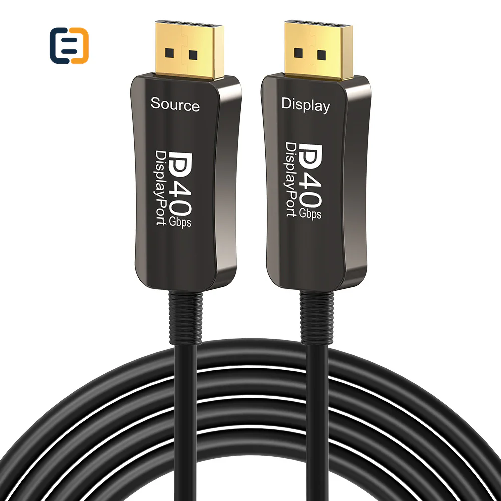
Fiber & Active OpticalSC-DTD-005
DP2.1 fiber optic cable - DisplayPort 2.1
- Length
- 1/2/3/5/10m/15m/20m/30m/40m/50m/60m/70m/80m/90m/100m
- Color
- Black
Reference MOQ10 pcs
Confirm interface, direction, distance, bend and pull conditions, endpoint compatibility and acceptance method before a cable enters the conduit.

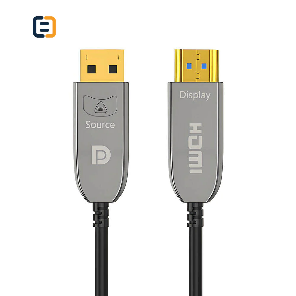
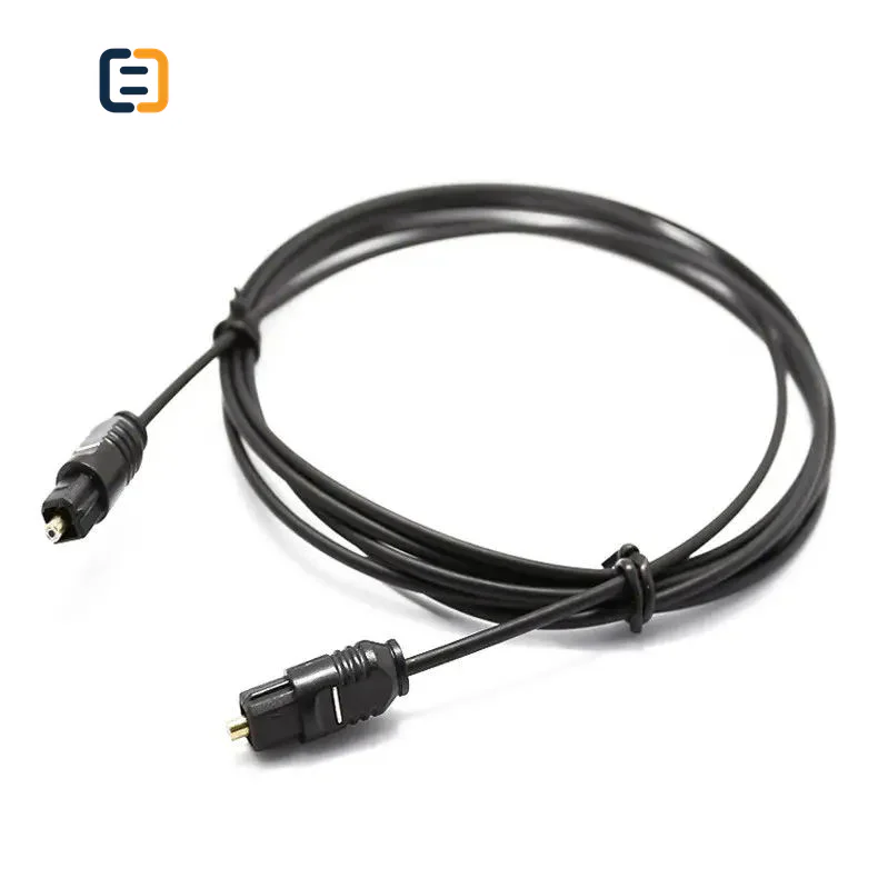
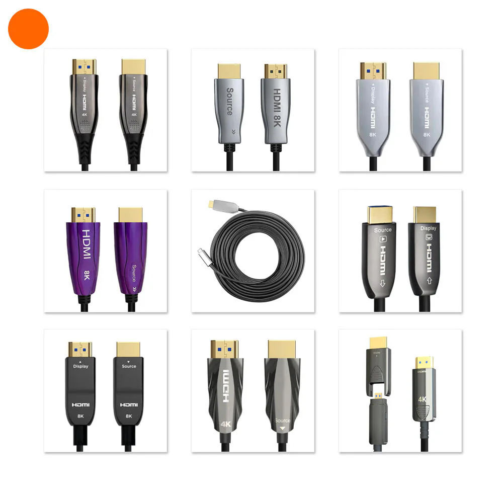
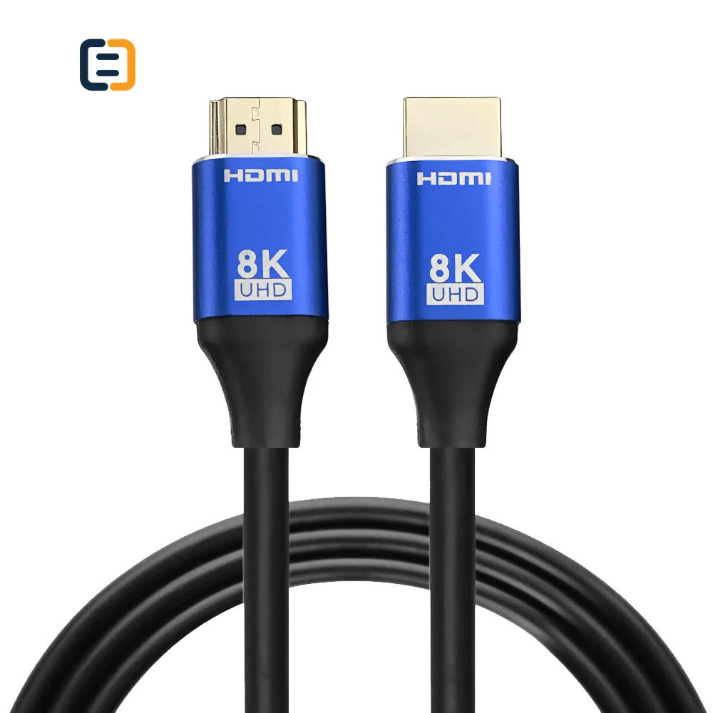
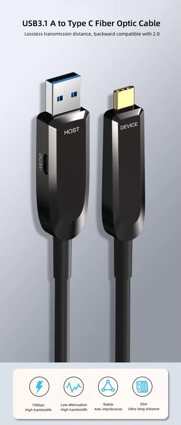
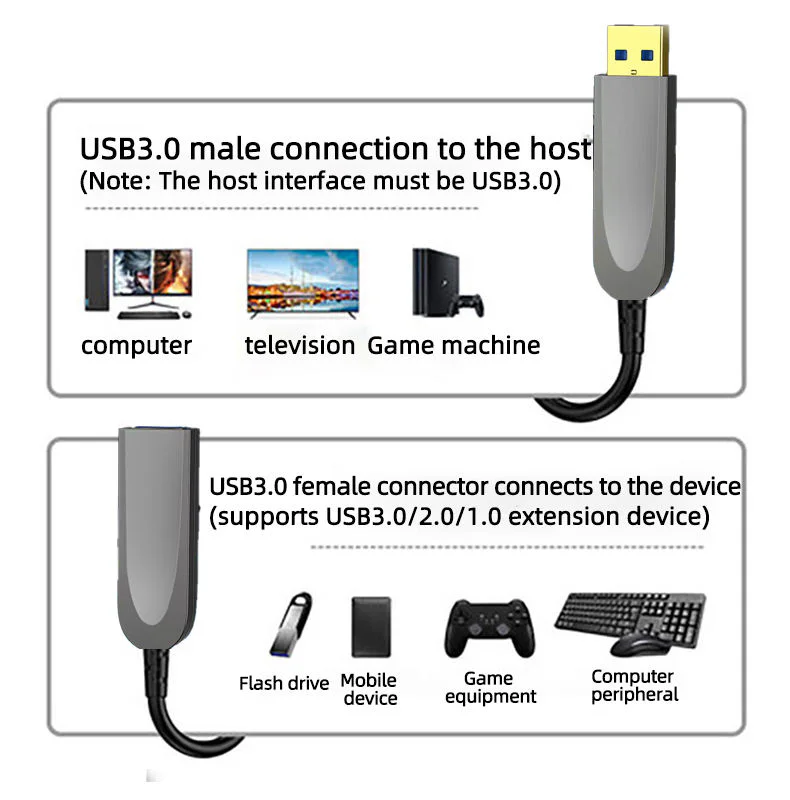
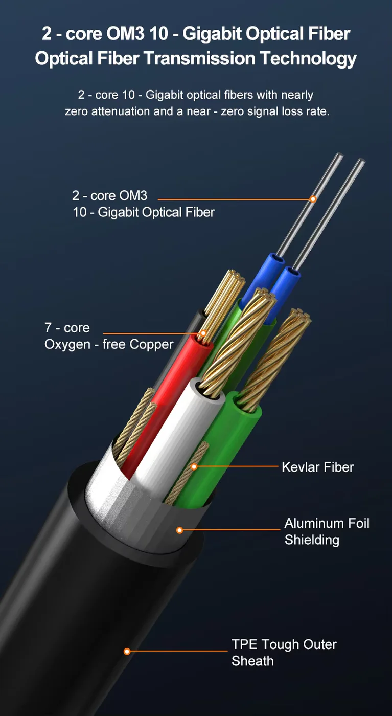
Every listed product remains available as a direct model page even when the visual catalog is paginated.
List the required variation, quantity, destination market and any evidence your buyer needs.
Active optical and fiber routes are selected by interface, signal direction, distance, installation path, bend constraints, connector protection and equipment compatibility. Confirm the complete route before ordering.
Use these routes to narrow the catalog. The final configuration is confirmed against the exact application and order.
Plan source/display direction, target signal mode, endpoint power and connector protection for long AV runs.
Filter relevant models02Match source, display, link workload, direction and bend constraints to the exact route.
Filter relevant models03Define host-device roles, data or peripheral workload, direction and any local power requirement.
Filter relevant models04Specify transceiver or extender set, fiber type, connectors, distance, power and service access.
Filter relevant modelsOpen a model page for its listed attributes, images and product-specific RFQ. These cards are starting points, not a claim that one model fits every route.
Active optical cable selection combines interface performance with direction, installation handling and serviceability at the final distance. These are requirement checks, not unverified claims about every catalog model.
Use the tabs as an RFQ checklist. Listed catalog attributes remain reference data until the exact model and order are confirmed.
Distance, conduit, bends and service access should be known before construction is selected.
Active optical assemblies are often directional and remain dependent on the endpoint equipment.
A cable that passes bench tests can be damaged by pulling force, tight bends or unprotected connectors.
Verify the route before the cable becomes inaccessible and again after termination.
Compatibility statements are meaningful only when tied to the final equipment, route, configuration and quoted model.
Plan model-specific evidenceUse the final application and quoted configuration. Keep the approved sample, result and open exceptions tied to the model and order.
 Packaging and identification planning
For active optical cable programs, identification and protection are functional parts of the product. The pack-out should preserve connector condition and tell installers how to pull, orient and validate the route.
Mark source and receiver ends on cable and pack.
Review caps, sleeves, pulling eye and dust control.
Use clear model, length and project identification.
Include handling, bend and acceptance notes where needed.
Final feasibility, MOQ, lead time and document availability are confirmed for the exact quotation.

One complete requirement brief gives engineering, purchasing and the supplier the same decisions to review.
Build a Requirement BriefUse these application planning scenarios to identify the equipment and acceptance conditions that belong in your RFQ.
Plan long source-to-display routes, conduit and endpoint recovery behavior.
Control direction, bend, service access and replacement stock across installed runs.
Match active interface route, environment and acceptance record to fixed equipment.
Validate the intended peripheral set, direction, distance and endpoint power together.
Certificate, report, drawing and catalog availability is checked by exact model, destination and order. These links are planning resources, not substitute evidence.
CoreCavo is operated by WUHAN SUNFULL. The public catalog organizes buyer requirements and model references; final specifications, commercial terms and applicable documents are confirmed through the exact quotation.
Map the Fiber / AOC interface, equipment, quantity and destination before selecting a route.
Separate listed attributes from compatibility, construction and document questions that need confirmation.
Use the quoted configuration, record results and retain open exceptions against the approved model.
Keep product code, labels, packaging and change-control requirements aligned through fulfillment.
Trace the real path through conduit, tray, risers, furniture and service loops. Add enough endpoint slack for termination without creating tight coils. Record conduit diameter, occupied sections and direction changes. Straight-line distance can underestimate the cable required and ignore the hardest pull. Choose the finished length from this route and state allowable excess management. If the cable will become inaccessible, consider replacement access and spare strategy before installation rather than after the first fault.
Identify the sending device and receiving equipment, connector format and highest required video, data or peripheral workload. Many active optical assemblies are directional; the source and receiver ends must be clear in the RFQ, on the product and during pulling. For USB or KVM routes, list peripheral classes and any local power. For AV, state resolution, refresh, color, audio and intermediary equipment. Optical transport does not remove endpoint negotiation or compatibility requirements.
Some active optical assemblies use fiber for high-speed signals and copper conductors for power or low-speed functions. Ask the supplier to identify the proposed construction and any endpoint or auxiliary power condition. Cable diameter, connector modules and active electronics affect handling and fit. For wall plates or tight enclosures, measure connector clearance. Test recovery after endpoint power cycles because a route that works continuously may behave differently when the source or receiver restarts.
Obtain the minimum bend guidance, permitted pulling method and connector-protection plan for the exact product. Avoid pulling directly on an exposed connector shell unless the design is intended for it. Use caps, sleeve or a pulling eye where specified, and keep dust away from optical interfaces. Plan bends at conduit entries and behind equipment. Installers should know direction before the pull starts; discovering a reversed assembly after a long concealed run can require complete removal.
Verify model, length, direction and connector condition, then test the required operating workload with representative endpoints. Include cold start and reconnect behavior. Record the result and label both ends. This check separates a product or compatibility issue from installation damage. For multiple identical routes, use a consistent pre-install checklist. A sealed package should not be treated as proof that the active electronics and connector modules survived transport or match the expected direction.
Control pulling force, bend and connector protection during installation. Before final connection, inspect shells, caps, cable jacket and strain relief. Test the full workload again after termination, including power cycles and any intermediary equipment. If performance changes, compare with the pre-install record and inspect the route before substituting components. Keep the final endpoint and route labels visible so service staff can identify source/receiver direction without opening drawings.
Long installed routes can be costly to replace. Decide whether a tested spare of the same model and length is justified, how it will be stored and how change control applies if the original design becomes unavailable. Handover should include route, model, length, direction, endpoint equipment, acceptance result and known exceptions. Store connectors protected from dust and mechanical damage. This is more useful than generic inventory labeled only ‘optical HDMI’ or ‘USB fiber.’
Provide interface, source and receiver, workload, route length, conduit and bend conditions, pulling method, connector protection, power, labels, quantity, spare requirement, packaging and evidence needs. Ask the supplier to state direction, construction and handling limits. Define pre-install and post-install acceptance responsibility. This makes commercial comparison reflect the delivered installation package rather than only a distance number and helps avoid a low-cost cable becoming an expensive site rework.
If a route later needs another length or replacement, compare the new proposal against endpoint models, direction, workload, bend and connector-clearance data from the original handover. Do not assume a newer active module behaves identically because the outer cable looks the same. A concise route register helps purchasing select a compatible spare, gives installers the handling information they need and provides a rational trigger for revalidation when construction or electronics change.
Use these procurement priorities to compare the proposed model, approval conditions and repeat-order requirements.
Buyers need direction marks, connector protection and bend guidance before the route is pulled, not after a failure inside conduit.
Active designs can vary by interface and length, so model-level bench and post-install checks should identify the supplied assembly.
A long optical path still depends on source, display or peripheral behavior and should be approved with representative endpoints.
Project handover should include route labels, accessible service loops, exceptions and a spare strategy for difficult installations.
Answers separate catalog references from decisions that require an exact route, model and RFQ.
Provide interface, source and receiving equipment, signal or data workload, measured route length, conduit and bend conditions, pulling method, connector clearance, direction, power behavior, quantity, labels, packaging and acceptance checks. Add spare and document requirements where relevant. Distance alone is not enough to select an installation-ready route.
Many are directional because active electronics are assigned to source and receiver ends. Confirm the exact product, then mark direction in the quotation, on both ends and on packaging. Verify orientation before pulling through conduit. Do not assume reversibility from identical-looking connector shells.
A pre-install bench test confirms model, length, direction, connector condition and endpoint compatibility before the cable becomes difficult to access. Repeat the functional test after installation. Comparing the two records helps distinguish an existing compatibility issue from damage caused by pulling, bending or termination.
Excessive pulling force, tight bends, crushed cable, unprotected connector modules, dust and incorrect source/display orientation can cause failure. Obtain handling limits for the exact product and plan conduit entries, pulling protection and endpoint slack. Avoid treating a fiber-based assembly like an ordinary passive copper cable.
No. The route remains dependent on interface electronics, source and receiver behavior, the target workload, power and product design. Distance claims are conditional. Validate the exact model and length with representative equipment, and keep direction and installation constraints in the approval record.
For difficult or inaccessible routes, consider a tested spare with the same model, length and direction. Store connectors protected from dust and damage, and label the applicable route. If the original construction changes, review compatibility and handling before treating a new model as an automatic replacement.
Direction, model, length, project or room labels, connector protection and installation notes may be reviewed for suitable quantities. These elements should make handling safer without implying unverified performance. Final feasibility, MOQ, lead time and pack-out follow the exact interface, construction and route review.
Move from product comparison to compatibility, custom construction and required documents without restarting the sourcing process.
Include model codes where known, or describe the interface, equipment, length, quantity, destination, packaging and evidence requirements.