An active optical cable installation should be accepted as a controlled route, not merely as a cable that showed a picture once. Before pulling, identify the exact model and length, obtain its current installation limits, confirm the Source and Display ends, survey every pathway transition, protect the connector assemblies, and run a functional test with the intended equipment and operating mode. After pulling, repeat the same test and record the result against the pre-pull baseline. Handover should include the as-built route, direction labels, product identity, test conditions, accessible endpoints, and a replacement plan. There is no safe universal bend radius, pulling tension, or maximum distance for all AOCs. Product-specific limits come from the exact manufacturer instructions and approved method statement, subject to applicable codes, contract requirements, and the authority having jurisdiction.
A defensible acceptance record is a chain of linked evidence. Each record answers a different question:
- Did the delivered assembly match the approved submittal?
- Could the proposed route accommodate its connector heads and mechanical limits?
- Did the assembly work before it entered the pathway?
- Was it installed using the approved direction and handling method?
- Did it deliver the same required functions after the pull?
- Can another team identify, isolate, and replace it later?
A single photograph of a powered display cannot answer all six.
Treat the AOC as an assembly, not bulk fiber
An AOC is normally delivered with factory-terminated connectors and active electronics. Some designs use optical channels for high-speed data while retaining copper conductors for power or other functions; product construction varies. The connector ends may contain optical-electrical conversion, retiming, or protocol electronics that cannot tolerate the same handling as ordinary bulk cable. They may also be physically larger than the cable body and larger than a conduit path that looked adequate on a drawing.
This has four practical consequences.
First, the exact product identifier matters. A family name or interface label does not define connector-head dimensions, pulling method, direction, power source, bend limits, or sideband functions. The site team needs the approved model, length, construction revision where available, and current installation document.
Second, damage can occur without obvious jacket failure. A connector shell can be cracked, internal termination strained, or electronics exposed to excessive force while the outer cable still appears normal. Visual inspection is necessary but cannot replace a functional comparison.
Third, field termination assumptions are risky. A pre-terminated AOC is not automatically repairable using ordinary fiber splicing or connector tools. If the manufacturer does not document a field-repair method, plan for replacement of the assembly.
Fourth, interface capability and installation acceptance are separate. An official cable certification, where one exists for the exact model and length, addresses the relevant certification program. It does not prove that the route survey was correct, that the cable was not damaged during pulling, or that the site's source, display, dock, switch, or control features are compatible.
Build one installation control record
Rather than distributing evidence across email threads, create a control record for each installed run or clearly identified group of identical runs. It can be a commissioning sheet, digital form, or project database entry, but it should retain the following fields:
- project, room, rack, source endpoint, and destination endpoint;
- approved manufacturer, model, assembly length, and revision or production identifier if supplied;
- serial or batch information where available;
- interface and exact required operating mode;
- required audio, control, return-channel, USB, or other auxiliary functions;
- Source-end and Display-end marking;
- approved route drawing and pathway identifier;
- manufacturer document revision used for installation limits;
- receiving-inspection result;
- pre-pull test equipment, settings, result, operator, and date;
- installation method, pull direction, protection method, and crew;
- any deviation, stop-work event, or observed damage;
- post-pull test equipment, identical settings, result, operator, and date;
- endpoint label and as-built route reference;
- spare or replacement approach;
- final acceptance, exception, or hold status.
The record does not need to be complicated. It needs to be traceable. A future technician should be able to tell which assembly was installed, how it was tested, and which assumptions were accepted.
Hold Point 1: approve the exact cable submittal
Do not release a cable for pulling from a generic description such as “long HDMI fiber cable” or “DisplayPort AOC.” The submittal should identify the exact assembly and answer the site questions that affect installation.
Direction and endpoint labels
Many active optical assemblies are directional. The labels may use Source/Display, TX/RX, Input/Output, or equipment icons. Confirm the manufacturer's terminology and reproduce it on the route plan. If labels are small or will be hidden after installation, add durable project labels without covering required regulatory or product markings.
Direction is a functional requirement, not a preference. Pulling a directional assembly backward can leave the wrong connector at each endpoint. Reversing the run later may be impossible after ceilings close or furniture is installed. The method statement should show which connector enters the pathway first and where each end will land.
Mechanical installation limits
Obtain the exact model's limits for pulling load, loaded bend behavior, installed bend behavior, twisting, crushing, connector handling, and any permitted pulling accessory. Do not copy a number from another manufacturer's AOC, another length in the same marketing family, or a bare-fiber installation guide. Product construction and connector design can change the allowable method.
If the data sheet does not contain enough installation information, request a manufacturer installation instruction or written clarification before release. “Install carefully” is not an auditable mechanical limit.
Power and functional scope
Determine how the electronics are powered. Some assemblies draw power from the interface; others may use auxiliary power. Confirm that the actual endpoints provide the required behavior and that any external supply can be installed, accessed, and replaced.
List every function required at acceptance. For a video link, that may include a precise resolution and refresh rate, color/HDR behavior, audio, HDCP-protected content, CEC, ARC/eARC, or Ethernet-related functions, depending on the interface and product. For a DisplayPort or USB optical assembly, the required link rate, USB data behavior, video mode, or auxiliary capability may differ. Do not assume that carrying the primary picture or data stream proves all sideband functions.
Certification and environmental evidence
If the specification requires an HDMI or VESA certification, fire-performance classification, material declaration, or other evidence, request it for the exact model, length, and construction. HDMI Licensing Administrator explains that cable certification programs test defined models and lengths; a result for one assembly should not be stretched across unverified variants. The same evidence discipline applies to product database listings and labels.
Environmental suitability must be checked against the route. Ceiling spaces, air-handling spaces, risers, outdoor transitions, equipment enclosures, temperature conditions, chemical exposure, and local code can impose different requirements. This article cannot select a fire rating or approve a jurisdiction. The project's qualified designer and authority requirements control.
Hold Point 2: survey the route in three dimensions
A drawing can show distance while hiding the conditions most likely to damage a connectorized assembly. Walk the actual route before the cable is unpacked for installation. If access is incomplete, keep the release on hold.
Trace every transition
Record entry and exit points, bends, offsets, pull boxes, tray changes, sleeves, conduits, floor penetrations, cabinet openings, and furniture interfaces. Check the route in the intended pulling direction. A connector may pass through a straight section but fail at a bend, offset, crowded junction, or entry fitting.
Measure or verify the limiting clearances against the protected connector head and any manufacturer-approved pulling sleeve or eye—not only against the cable outside diameter. Account for existing occupants in shared pathways and the approved fill or separation rules. Do not improvise by removing a factory connector shell unless the manufacturer provides a documented removable-head procedure for that exact product.
Check bend control where the route changes direction
Identify every point where the assembly could be bent under pulling load and every point where it will rest after installation. Manufacturer material commonly distinguishes conditions during pulling from conditions after installation. The approved method must respect the exact product's stated limits in both states.
Avoid converting a product limit into a visual guess such as “a gentle curve.” Show how the crew will control the bend using the pathway geometry, approved guides, rollers, or other specified aids. If the route cannot maintain the required geometry, redesign the route or select a reviewed alternative before pulling.
Identify force, snag, and crush hazards
Look for sharp edges, burrs, tight fittings, congested pull boxes, cable ties that may be over-tightened, tray covers, access doors, ceiling-grid edges, pinch points, and locations where another trade could step on or load the cable. Confirm how communication will be maintained between feed and pull teams so work stops immediately if resistance changes.
Pulling force cannot be inferred reliably from how hard a technician feels they are pulling at one end. Use the manufacturer's permitted method and any required monitoring. Never attach the pulling line directly to a connector body unless that exact approach is documented. Do not use lubricant, powered pulling equipment, or a shared pull bundle unless allowed by the product instructions and approved method statement.
Plan the termination space
At both endpoints, check connector insertion clearance, bend transition away from the port, strain relief, service access, equipment-door movement, and ventilation. The cable should not hang from a device port or be forced into an immediate unsupported bend. If an adapter, wall plate, coupler, patch field, or extension is proposed, add it to the complete compatibility and acceptance test; it changes the link.
Survey replaceability now
Ask how the assembly would be removed if it failed after handover. Verify access to both connector heads, pathway continuity, pull-box availability, route occupancy, and whether a future pulling line or approved draw path is retained. If replacement would require demolition, that is a project risk to document before acceptance, not a maintenance surprise.
Replaceability may be improved through an accessible pathway, suitable spare capacity, an approved spare run, or a modular architecture. The correct choice depends on project cost and criticality. Do not promise “easy field repair” unless the exact product has an authorized repair method.
Hold Point 3: inspect and baseline-test before pulling
Pre-pull testing separates delivery condition from installation outcome. It should happen after receiving inspection but before the assembly enters the route.
Receiving inspection
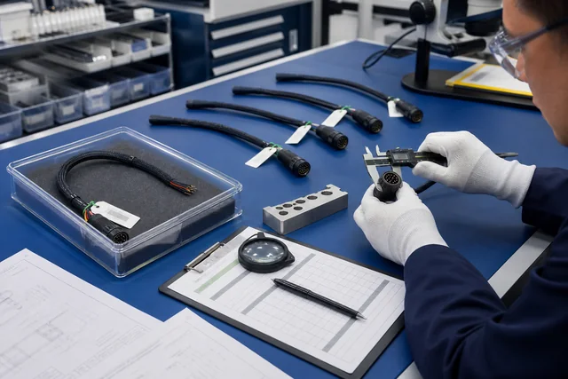
Match the label to the approved submittal: model, length, connectors, direction, and required markings. Check packaging for impact, crushing, water, or tampering. Inspect connector shells, pins or mating surfaces as appropriate, strain reliefs, dust caps, jacket, pulling accessories, and labels. Keep protective caps in place until connection or approved preparation.
Quarantine a mismatched or visibly damaged assembly. Do not “see if it works” and then install it without disposition; the acceptance record would no longer show whether a known defect was accepted.
Build a representative bench path
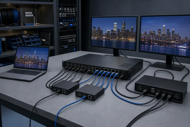
Use the intended source and destination models whenever practical. If exact project equipment is unavailable, record the substitute and treat the result as conditional. Include any required switcher, extender, dock, KVM, wall plate, coupler, or receiver that will remain in the final path.
Set the exact required operating mode rather than accepting an automatic lower mode. For a video AOC, record resolution, refresh rate, color/HDR settings, audio, and protected-content test where applicable. For a data or USB AOC, define the required protocol operation and representative device workload. Test the auxiliary functions named in the specification; a visible desktop alone does not prove audio, control, return channel, USB, or network behavior.
Exercise startup and operational transitions relevant to the project: cold start, source and display power sequence, reconnect, wake from sleep, and stable operation for the project-defined observation period. Record endpoint firmware and operating-system versions if they can affect the result.
Preserve a comparable baseline
Photograph the product label and direction markings, but do not rely on photographs alone. Save the test settings, equipment IDs, connections, result, and any observed limitation. The post-pull test should use the same equipment, configuration, content or workload, and acceptance threshold so that the two results can be compared.
A continuity light or generic cable tester may not exercise the active protocol electronics or the required operating mode. Use test equipment and methods appropriate to the finished assembly, following the manufacturer and project test plan. Do not open a connectorized AOC to perform bare-fiber measurements unless the product instructions explicitly support that procedure.
Hold Point 4: control the pull
The installation supervisor should conduct a brief release check immediately before the pull:
- correct cable and route confirmed;
- Source and Display ends assigned to their destinations;
- route complete and clear;
- connector protection fitted using the approved method;
- bend and pulling controls ready;
- feed and pull teams positioned with communication established;
- no unapproved bundle, lubricant, pulling tool, or connector modification introduced;
- endpoint protection and temporary support ready;
- control record open for observations.
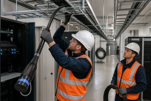
During feeding, protect the connector and prevent the assembly from twisting. Feed the cable in the orientation required by the pulling arrangement and maintain the manufacturer's bend rules. Keep the cable away from sharp surfaces and do not allow a coil to collapse into a kink. If resistance changes unexpectedly, stop. Increasing force to overcome an unknown obstruction can turn a recoverable route issue into hidden assembly damage.
At intermediate access points, guide the protected connector through rather than allowing it to strike fittings or drop. Manage slack without walking on, crushing, or sharply folding the cable. Temporary ties and supports should not deform the jacket. Any event outside the approved method—snag, excessive force indication, dropped connector, damaged cap, unplanned bend, water exposure, or pathway change—belongs in the record and triggers the project's hold/disposition process.
After the pull, support the assembly and connector transition before mating it to equipment. Remove protection according to the product instruction, inspect the connector ends, and retain or replace caps if final connection is delayed. Do not leave active electronics hanging by the cable or device port.
Hold Point 5: repeat the test after installation
The post-pull test should mirror the pre-pull baseline. This is what gives the acceptance result meaning.
Connect the same source, display or device set where possible. Restore the recorded mode and verify every required function. Repeat cold start, reconnect, sleep/wake, protected-content, audio/control, or data workload checks defined before the pull. Observe the link under its final physical arrangement, including approved intermediaries and power supplies.
Record one of three dispositions:
- Accept: identity, installation record, and all required pre/post tests match the approved criteria.
- Conditional acceptance: an explicitly documented deviation is approved by the authorized project party, with ownership and closure date.
- Hold/reject: identity is wrong, handling limits were exceeded or unknown, physical damage is present, required function fails, or evidence is incomplete.
Do not lower the test mode until an image appears and then call the cable accepted. A lower fallback may help diagnose the path, but it does not meet a higher specified operating point. Likewise, do not accept only the primary signal when the approved requirement includes audio, HDCP, CEC, eARC, USB, or another feature.
An acceptance matrix for the site file
| Stage | Release question | Minimum evidence | Hold condition |
|---|---|---|---|
| Product submittal | Is this exact model and length approved? | Data sheet, installation instruction, direction, functional scope, required evidence | Generic family claim or missing mechanical instructions |
| Route survey | Can the protected connector and assembly pass without violating product limits? | As-surveyed route, limiting clearances, transitions, access and replacement review | Unsurveyed transition, inadequate clearance, uncontrolled bend or inaccessible endpoint |
| Receiving | Did the delivered unit match the submittal and arrive undamaged? | Label/identity record and inspection result | Mismatch, damaged packaging or assembly, missing direction marking |
| Pre-pull test | Did the assembly meet the required mode before installation? | Equipment, settings, functions, results, operator/date | Untested unit, substitute setup not approved, incomplete function test |
| Pull | Was the approved method followed? | Crew release check and exception log | Snag, excessive or unknown force, unapproved method, connector impact or route change |
| Post-pull test | Does the installed link match the baseline and requirement? | Repeated test with comparable conditions | Failure, fallback mode only, intermittent behavior or missing required function |
| Handover | Can operations identify and replace the run? | As-built record, labels, evidence set, access and replacement plan | Untraceable cable, hidden direction, missing record or no agreed replacement path |
Diagnose a failed post-pull test without destroying evidence
If the installed link fails, preserve the control record and avoid immediately pulling the cable back out. A structured check can distinguish configuration, direction, power, endpoint, and physical-route issues.
- Confirm that the correct Source and Display ends landed at the documented endpoints.
- Confirm power to endpoints and any auxiliary supply.
- Restore the exact pre-pull source, display, settings, and intermediaries.
- Check connector seating, port selection, and visible damage without opening the assembly.
- Compare the negotiated or displayed operating mode with the baseline.
- Bypass newly introduced intermediate devices only if the test plan permits and document the change.
- Review the pull log for snags, impacts, route deviations, or uncontrolled force.
- Follow the manufacturer's troubleshooting and return process before destructive examination.
Intermittent results are not acceptance. Record when the failure occurs—cold start, wake, cable movement, high operating mode, protected content, audio return, or sustained workload. The pattern helps the responsible supplier or integrator investigate without replacing facts with guesses.
Handover must make the run maintainable
Commissioning is complete only when the operations team can identify and manage the installed link. The handover package should include:
- final cable identity, quantity, installed locations, and direction;
- as-built pathway and endpoint labels;
- current product and installation documents used for approval;
- receiving, pre-pull, pull-event, and post-pull records;
- required operating mode and confirmed auxiliary functions;
- endpoint equipment and relevant firmware or settings;
- exceptions and approved deviations;
- warranty, support, and return information;
- access instructions for connector heads and intermediate points;
- approved cleaning or inspection guidance, if applicable;
- spare, replacement, or downtime plan for critical runs.
If the installed model is later replaced by a “similar” AOC, repeat the review. A different assembly may have different connector dimensions, direction markings, power behavior, functions, certification status, and mechanical limits even when the interface and advertised resolution look identical.
For critical paths, decide who owns the spare and how it will be stored. A spare should remain identifiable and protected, and its usability should be confirmed under the project's maintenance policy. Avoid assuming that an unopened spare remains equivalent indefinitely when firmware, endpoint fleets, or product revisions change.
Risks that deserve an explicit owner
Direction risk: the assembly is pulled backward or the labels become inaccessible. Owner: installation supervisor; control: route drawing, pull-direction release, durable endpoint labels.
Connector-clearance risk: the cable body fits but the protected connector cannot pass a transition. Owner: route designer or contractor; control: physical survey against the exact head and pulling accessory.
Mechanical-limit risk: another model's bend or pulling value is reused. Owner: submittal reviewer; control: exact-model document and approved method statement.
Evidence-gap risk: no comparable pre-pull baseline exists. Owner: commissioning lead; control: recorded representative test before installation.
Feature-scope risk: the picture works but a required control, audio, return-channel, USB, or protection function does not. Owner: system designer; control: written acceptance matrix covering every required function.
Damage-without-visible-mark risk: the jacket looks normal after a snag. Owner: installer and commissioning lead; control: exception log, hold point, repeated full-function test, manufacturer disposition.
Replacement risk: connector heads become inaccessible after finishes close. Owner: project designer and facilities team; control: maintainable pathway, access plan, and agreed spare/replacement strategy.
Certification-assumption risk: evidence for one model or length is applied to another. Owner: procurement and quality; control: exact-model/length traceability and certificate or database verification.
Request an installation-aware AOC review
For an AOC project review, provide the interface, exact video or data mode, cable length, route drawing or survey, connector-head clearance, pathway transitions, installation environment, source and destination models, required auxiliary functions, evidence requirements, quantity, and replacement expectations. Use the Fiber & Active Optical category only as a model-family starting point, and use the test and compliance documents guide to define the evidence requested for the exact construction and length. CoreCavo can use those inputs in an installation-aware RFQ. Final performance, direction, mechanical limits, documentation, MOQ, and installation method must be confirmed for the exact quoted model and length. This guide does not approve a route, certify a product, or replace the manufacturer's instructions and the project's qualified installer.
Official and Primary Sources
- HDMI Licensing Administrator, HDMI Cable Types. Used for official cable-category and certification context; it does not establish a universal installation limit.
- HDMI Licensing Administrator, HDMI Technology and Specification Overview. Used for official active/passive cable and Cable Power background. Product construction, direction, usable length, and mechanical limits must instead come from the exact model documentation and approved installation method.
- HDMI Licensing Administrator, Premium HDMI Cable Certification Program. Used for model/length-specific certification discipline, not as evidence that any CoreCavo product is certified.
- Video Electronics Standards Association, DisplayPort Cable and Adaptor Certification Program. Used for DisplayPort certification context.
- VESA, DisplayPort Product Database: Cables and Adaptors. Used as the official verification route for listed DisplayPort products rather than relying on an unverified logo claim.
- Extron, HD Pro Plenum Active Optical HDMI Cable. A primary manufacturer example showing that an exact AOC can have defined direction, connector construction, power behavior, bend limits, pulling limits, and installation accessories. No numerical value from this product is generalized in this guide.
- Extron, HD Pro Plenum Product Announcement. Primary manufacturer context for a hybrid optical/copper, directional, source-powered construction; cited only to demonstrate that AOC architecture is product-specific.
- Corning Optical Communications, General Installation Guidelines for Fiber Optic Cable. Primary manufacturer guidance for route planning, bend control, pulling tension, conduit considerations, and installation handling. Numerical limits must come from the selected product's documentation.
- Corning Optical Communications, Standard Recommended Procedure 005-014. Primary manufacturer guidance for protecting cable and connectors and respecting loaded and installed mechanical limits; it is not a substitute for the selected AOC's instruction.