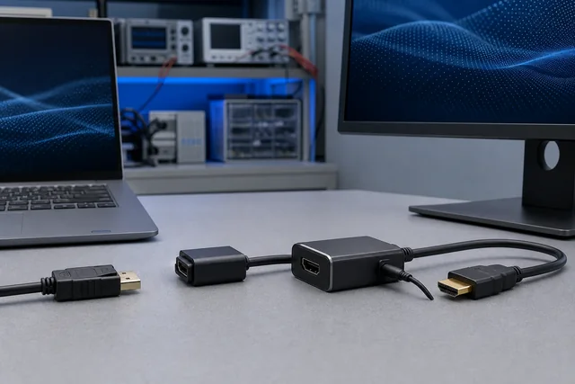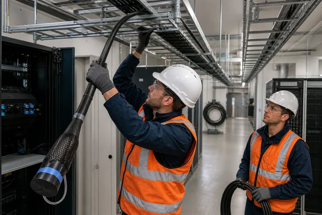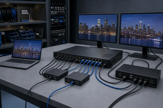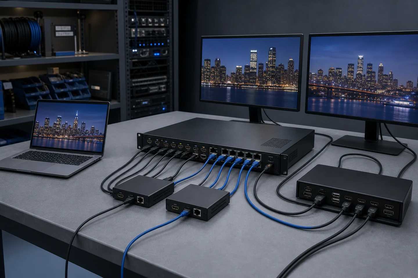
Buyer Direct Answer
Start an HDMI splitter vs switch comparison by drawing the signal topology before comparing model names. Use a splitter when one source must feed multiple destinations, a switch when several sources share one destination, a matrix when several sources must be routed independently to several destinations, an extender when a defined signal must cross an installed distance, and a KVM when an operator must control a computer as well as view its video. A real project may need more than one of these functions. The quotation should therefore describe the complete source-to-destination route, simultaneous operating states, cable infrastructure, USB or control path, power locations and acceptance tests.
Scope, Boundaries and Responsibility
This guide is a procurement framework, not a finished system design. It does not state that every splitter, switch, matrix, extender or KVM listed by CoreCavo supports every function discussed below. It also does not replace the instructions, specifications, firmware notes or certification records for the exact source, display, endpoint and distribution model.
Resolution and connector names are not enough to approve a route. Color format, refresh rate, content protection, display identification, audio behavior, USB class, control method, cable construction, installed distance and endpoint power can all change the result. The buyer or responsible integrator must confirm the applicable requirements and test the final equipment set.
This article deliberately does not reproduce the catalog on the AV Distribution & Extension category page. Product cards should be treated only as candidate models requiring confirmation. A listed product name is not evidence that the model is suitable for a particular topology, distance, format or simultaneous-use condition.
Start With Arrows, Not Boxes
An AV diagram becomes useful when every arrow has a defined origin, destination and purpose. Before writing “need a 4K splitter” or “need an HDMI matrix,” list the equipment that sends and receives each signal.
For every source, record:
- The source type and exact model planned for validation.
- The output connector and the highest required video and audio mode.
- Whether protected content, wake/sleep behavior or automatic source switching matters.
- Whether the source must also carry USB, network or another control channel.
For every destination, record:
- The display, projector, recorder, capture device or remote workstation role.
- The input connector and required operating mode.
- Whether every destination must show the same content or select content independently.
- Whether the destination returns audio, USB, control or status information.
Then label each arrow with the installed medium and distance. An HDMI patch lead, in-wall copper cable, active optical cable, Category-cable extender and AV-over-IP network are not interchangeable just because they can appear between the same source and screen. Each route has different endpoint, handling, power, infrastructure and service requirements.
Finally, draw the operating states. A diagram that shows four sources and four displays still does not say whether all outputs must work at once, whether any display may select any source, or whether only one fixed presentation mode is needed. Those states determine whether a basic distribution device is enough or a routable system is required.
Five Device Roles in One Topology Map
Splitter: one source, multiple destinations
A splitter begins with one source and creates more than one output. It is appropriate when the same program must reach several displays or downstream devices at the same time. Examples include a reception display wall showing one player, a training room mirroring one computer, or a demonstration bench feeding both a local monitor and a recorder.
The important procurement question is not only the output count. Ask what must happen when destinations report different supported formats, when one display is disconnected, or when protected content is used. State whether all outputs must remain active and whether the system may fall back to a common mode. A quotation should also identify whether local cables, remote extenders or mixed endpoint types are included.
Switch: multiple sources, one destination
A switch allows one destination to select among several sources. It suits a room where a display must alternate between a room PC, a laptop, a media player or another input. The buyer should define how selection occurs: front-panel button, remote control, automatic sensing, serial command or another method.
Automatic switching is an operating rule, not a universal feature. Describe the required priority, what should happen when a source sleeps, and whether the last selected input should return after power recovery. If switching time or visible blanking affects the application, make that an acceptance scenario rather than assuming all models behave alike.
Matrix: multiple sources, multiple destinations
A matrix provides independent routing between multiple inputs and outputs. The shorthand “4x4” or “8x8” describes connector counts, but it does not fully describe use. A buyer must state whether every output may select any input, how many different sources must be displayed simultaneously, whether routes are fixed or changed frequently, and how users or a control system issue commands.
Matrix projects also need a failure model. If one output is changed, must the other outputs remain stable? If one display is powered off, may that affect a different room? Are presets needed for known events? Is audio embedded with video, broken out separately, or routed by a different system? These are system questions that should be documented before comparing quotations.
Extender: a transport layer across distance
An extender moves a defined signal between a transmitter and receiver across an installed medium. It may use Category cable, fiber or another transport route. An extender does not automatically provide source selection or multi-output routing. It can sit before or after a switch, splitter or matrix, which is why distance and topology should be documented separately.
For an extender quotation, identify the transmitter and receiver as a pair, the installed cable type, termination method, patching, maximum project distance, intermediate connections, power location, accessories and service access. Do not adopt a distance number from a different model or a marketing summary. The HDBaseT Alliance, for example, publishes different capabilities and cable recommendations across generations; the exact devices and installed channel still require confirmation.
KVM: video plus operator control
A KVM route combines video with keyboard and mouse control and may include other USB functions. The word “KVM” does not define the USB class, data rate, peripheral support, number of users or switching behavior. A basic keyboard and mouse route is not the same requirement as a camera, storage device, touch display, audio interface or other USB peripheral.
List every peripheral, the host operating system, any driver restriction, the required USB behavior and whether control must remain available while video routes change. If several computers and several operator stations are involved, show both the video path and the USB/control path. They may not switch in the same way.
The Topology Worksheet That Should Precede an RFQ
Use the following fields to normalize the project before asking suppliers for models.
| Decision field | What the buyer should define | Why a connector count is not enough |
|---|---|---|
| Sources | Exact equipment, output connector and required mode | Sources can differ in format, protection, hot-plug and sleep behavior |
| Destinations | Exact displays, recorders or endpoints | Mixed destinations may not report or accept the same modes |
| Simultaneous state | Which inputs and outputs operate at the same time | A device may work in a single-path demo but fail the required combined state |
| Routing rule | Mirrored, selected, independently routed or preset | This separates splitter, switch and matrix intent |
| Video and audio | Resolution, refresh, color, HDR and audio requirements | “4K” alone leaves several link variables undefined |
| Content protection | Protected sources and required system behavior | Every active device in the path must be reviewed for the actual use |
| Distance and medium | Finished length, installed channel and patch points | Endpoint capability and cabling form one transport route |
| USB and control | IR, serial, USB classes, network and control method | These functions are optional and can have separate limits |
| Power | Outlet locations, endpoint power and recovery behavior | A workable bench setup may not match the installed room |
| Operations | Switching, restart, sleep/wake and reconnect scenarios | Normal operation includes transitions, not only a static picture |
| Service | Access, spare strategy, firmware records and replacement steps | A hidden endpoint can turn a small failure into a large site visit |
| Evidence | Exact model, accessories, reports and acceptance record | Generic brochures cannot release a project configuration |
The completed worksheet should be revision controlled. If an integrator changes a projector, dock, cable route or control method, the change should be reviewed against the topology rather than treated as an isolated substitution.
A Practical Decision Sequence
Decision 1: How many independent sources and destinations exist?
Count logical sources and destinations, not just visible connectors. A computer with two independently used outputs may create two source paths. A display wall controller may appear as one destination to an upstream source even though it drives several panels. Record what the upstream device actually sees.
If there is one source and several destinations showing the same content, begin with a splitter route. If there are several sources and one destination, begin with a switch route. If there are several of each and outputs require independent selection, begin with a matrix route. These are starting roles; distance or operator control may add extender or KVM functions.
Decision 2: Must outputs operate independently?
“Four displays” can mean four copies of the same source, four independent source selections, or a scheduled combination of both. Write at least three normal operating examples. For a matrix, include a state where several outputs select different inputs and a state where several outputs select the same input. This reveals routing and control requirements that a port-count comparison misses.
Decision 3: Is distance changing the transport layer?
Map each installed segment. Include equipment-rack patch cables, wall plates, couplers, floor boxes and endpoint leads. If an extender is proposed, specify where conversion occurs and who supplies the installed medium. The route should be accepted as a channel, not as an isolated transmitter/receiver pair tested only with a short shop cable.
Decision 4: Does the operator need control or USB?
IR pass-through, serial control, network management and USB are different functions. State who sends each command, which device receives it, and whether the path is one-way or bidirectional. For USB, list the actual peripherals and required simultaneous operation. Avoid writing “USB support” without a host, device and use case.
Decision 5: What must happen during transitions?
Static operation is only one state. Include cold start, source change, display power cycle, cable reconnect, host sleep/wake and power interruption where relevant. Define the acceptable recovery behavior. If an operator should not need to visit a locked equipment room, make remote recovery and status visibility part of the requirement.
Compatibility Is a Chain, Not a Badge
Display identification and common-mode decisions
Sources and distribution devices use display information to determine supported modes. In a multi-display system, mixed capabilities can produce a common-mode decision or model-specific management behavior. The RFQ should identify the actual displays and state whether a lower-capability destination may reduce the mode delivered elsewhere. Do not promise a universal outcome without reviewing the exact distribution device.
Content protection across active devices
Protected content introduces requirements across the source, every active distribution component and the destination. Digital Content Protection LLC publishes HDCP specifications for HDMI, DisplayPort, HDBaseT and other adaptations. A buyer should identify the protected source and required content scenario, then request model-specific support and test it end to end. A connector label or general “HDCP compatible” phrase is not a complete system acceptance record.
Bandwidth, format and cable route
Resolution is only the visible part of a format. Refresh rate, color format, bit depth, HDR and compression can change the required path. HDMI Licensing Administrator publishes official cable categories and certification information, but a cable category does not upgrade a source, distribution device or display. Define the complete operating mode and request evidence for every active device and production cable length.
Audio, return paths and breakout
State whether audio remains embedded, is extracted locally, returns from a display, or is handled by a separate system. Define required channels and formats at the system level. If an output feeds a recorder or conferencing codec as well as a display, include that simultaneous state in acceptance testing.
Control, network and USB coexistence
Do not infer control or USB behavior from the transport connector. HDBaseT generations, for example, have defined feature sets that can include video, audio, Ethernet, control, power and, in certain generations, USB. USB-IF likewise distinguishes connector form from supported data and power capabilities. The proposed endpoints must identify which functions they implement and under what conditions.
Make Competing Quotations Comparable
Two quotations are not equivalent if they use different topology assumptions. Require each supplier response to return a one-page system schedule with the following items:
- Topology revision: the drawing or worksheet revision used for the proposal.
- Exact models: every main unit, transmitter, receiver, power supply, remote, mounting part and licensed feature.
- Included quantities: enough detail to identify whether each endpoint and accessory is present.
- Supported project state: the exact simultaneous routing, format, USB and control scenario proposed.
- Installed-medium assumptions: cable type, termination, patching, distance and any excluded infrastructure work.
- Power plan: local or remote power locations, included adapters and recovery behavior to be verified.
- Control plan: front-panel, remote, serial, network or third-party control dependencies.
- Evidence scope: manuals, declarations, program records or test information linked to the exact model.
- Open points and deviations: every requirement that is proposed differently or remains unconfirmed.
- Sample or pilot route: the equipment set, test location, responsibilities and acceptance record required before release.
Ask suppliers to mark each line as confirmed, proposed, deviated or open. This prevents a low quotation from looking comparable when it silently omits receivers, power supplies, control accessories, licenses or installation assumptions.
Validate the System as It Will Be Used
A useful sample review is a scenario test, not a photograph of powered equipment. Build an acceptance matrix from normal operation and known failure-sensitive transitions.
For a splitter, run every required output simultaneously with the intended destinations. Disconnect and reconnect one destination and observe whether the remaining required outputs behave as agreed. For a switch, select every source using every required control method, then test source sleep and restart. For a matrix, exercise independent routes, shared-source routes and stored presets without assuming success on one output proves the others.
For an extender, test the specified installed medium and full route, including patch points. Record endpoint power, direction and accessories. Test before installation when possible and repeat after the representative pull or final installation. For a KVM, operate the actual keyboard, mouse and any approved USB peripherals while the required video mode is active. Include host restart, login and sleep/wake if those events are part of daily use.
The acceptance record should identify:
- Topology drawing revision and test date.
- Source, destination and intermediary equipment models.
- Distribution models, endpoint roles and firmware references where available.
- Cable or installed-channel identity and length.
- Operating scenarios, expected result, actual result and open exceptions.
- Accessories and power supplies used.
- Person or organization responsible for approval.
A passed sample is evidence for the tested configuration. It is not a blanket claim for every cable, display, firmware version, distance or topology.
If the approval packet requires declarations, certificates, or test reports, use the Cable Test and Compliance Documents Guide to define what each document must identify and what it can actually prove.
Risk Register for AV Distribution Procurement
| Risk | Early warning | Control before order |
|---|---|---|
| Wrong device role | Port counts are listed but routing behavior is not | Approve a source-destination diagram and operating states |
| Mixed display fallback | Displays have different declared modes | Test all required destinations together and define acceptable fallback |
| Hidden accessory gap | Quote lists only the main chassis | Require a complete endpoint, power, mounting and control schedule |
| Transport mismatch | Bench demo uses a short cable instead of installed infrastructure | Validate the full channel at the project distance |
| Content-protection failure | Unprotected test content works but production content does not | Include the real protected-source scenario where authorized |
| USB overstatement | “KVM” or “USB” appears without peripheral details | List host, OS, device class and simultaneous peripherals |
| Control mismatch | Product can switch locally but the room requires remote control | Specify control method, commands, recovery and ownership |
| Power recovery problem | System works only after manual reseating | Test cold start, interruption and restart sequence |
| Change after approval | A model, firmware, cable or endpoint is substituted | Use revision control and require impact review or revalidation |
| Service access failure | Receiver or power unit is inaccessible after installation | Approve access, labeling, spare and replacement strategy |
Representative Product Families Are Starting Points Only
CoreCavo’s AV Distribution & Extension category contains splitter, switch, matrix, extender and KVM routes that can be reviewed against a completed topology worksheet. The presence of a product card does not confirm suitability for a project. Resolution, simultaneous outputs, distance, USB, control, power, accessories and evidence must be verified for the exact model and order.
Use HDMI Cables when the local copper segment needs model-and-length review. Use Fiber & Active Optical when a directional active optical assembly is being considered. These category pages are starting points, not statements that a catalog product meets the topology described in this article.
Buyer Questions
Can one device be both a switch and a splitter?
Some products combine functions, but the buyer should still describe the required input-to-output behavior. A combined label does not prove that every input can feed every output, that outputs are independent, or that the required simultaneous state is supported.
Is an extender the same as a splitter or matrix?
No. An extender primarily changes the transport path across distance. It can be combined with a splitter, switch or matrix, but it does not automatically add their routing behavior.
Does a 4x4 matrix guarantee four independent 4K outputs?
The port count alone does not prove the required simultaneous format, routing, content-protection or mixed-display behavior. The exact model, source set, display set and operating states must be reviewed and tested.
Why should the buyer list every USB peripheral for a KVM?
Keyboard and mouse control, storage, cameras, touch interfaces and other USB devices can have different data, power, class and operating-system requirements. “USB support” is too broad for a comparable quotation or acceptance plan.
What is the minimum useful sample test?
Use the intended source, destinations, installed-medium equivalent, cables, endpoints, power supplies and control method. Run the highest required mode and every required simultaneous state, then record startup, switching, reconnect and recovery behavior.
Next Procurement Step
Send a simple topology drawing with source and destination models, required simultaneous routes, signal format, installed distances, cable infrastructure, USB or control functions, power locations and sample acceptance scenarios. WUHAN SUNFULL can use that information to identify candidate product families that require model-level confirmation and to separate confirmed requirements from open technical questions.
Review AV Distribution Routes · Prepare a Controlled RFQ · Request a Project Review
Official Sources and Responsibility
These sources define relevant interface, protection and transport concepts. They do not certify any CoreCavo product or the topology in this guide.
- HDMI Licensing Administrator, HDMI Cable Overview: https://www.hdmi.org/resource/cables
- Digital Content Protection LLC, HDCP Specifications: https://www.digital-cp.com/hdcp-specifications
- HDBaseT Alliance, What Is HDBaseT Technology?: https://hdbaset.org/hdbaset-technology/
- HDBaseT Alliance, Products and Certification: https://hdbaset.org/products-certification/
- Video Electronics Standards Association, DisplayPort 1.4 Standard Overview: https://vesa.org/featured-articles/vesa-publishes-displayport-standard-version-1-4/
- USB Implementers Forum, USB Type-C Cable and Connector Specification: https://www.usb.org/usb-type-cr-cable-and-connector-specification