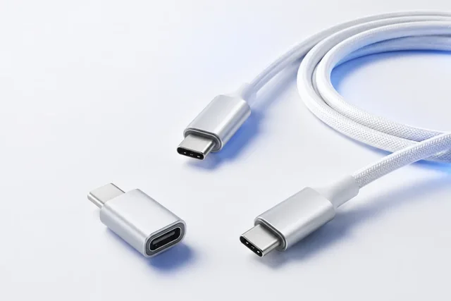
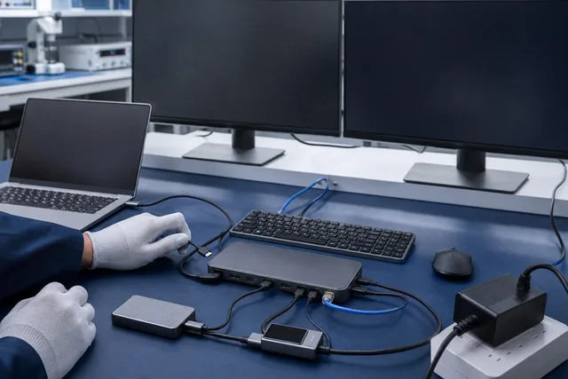
A USB-C cable power decision needs four independent bodies of evidence: identity, negotiation, delivery and temperature. Read the cable’s electronic identity where applicable, but do not approve it from the e-marker alone. Capture the USB Power Delivery contract, apply the exact approved load profile, measure voltage at defined points, observe connector and cable temperature under controlled conditions, and repeat the required cases in both plug orientations. Tie every result to one cable part number, revision, length, sample/lot identity, source, sink, analyzer, fixture, instrument version and ambient condition.
The pass limits must come from the exact applicable USB Type-C and USB PD specification revisions, the current USB-IF compliance documents, product safety limits and the buyer’s approved engineering requirement. This article intentionally does not publish a universal resistance, voltage-drop or temperature-rise threshold. The wrong number, test point or correction method can turn a plausible-looking test into unsafe or misleading evidence.
Loaded power testing—especially Extended Power Range operation—can expose personnel and equipment to high energy, hot connectors, arcing from damaged contacts and fire hazards. It must be planned and performed by qualified personnel using suitably rated USB PD analyzers, electronic loads or emulators, fixtures, leads, thermal instrumentation and protective controls, strictly within every source, sink, cable and instrument limit. Define emergency shutdown and stop conditions before energizing. Do not improvise a high-power test from consumer adapters, exposed conductors or unrated breakout boards.
Start with a release question, not a wattage slogan
“Can this cable do 240 W?” is not yet a test requirement. USB Power Delivery is a negotiated system involving a source, sink and cable. A useful release question names the operating envelope:
Does cable sample C, at the approved length and revision, support the required source-to-sink PD contract in both orientations, while meeting the applicable electrical and thermal acceptance criteria through the defined duration and recovery cases?
Expand that question on a sample test card:
| Test-card field | What to record |
|---|---|
| Cable identity | Controlled part number, revision, nominal length, sample/lot ID, connector markings and photographs |
| Construction class | Passive/active; USB-C to USB-C; declared data/power category; captive or detachable status |
| Electronic identity | Raw and decoded Discover Identity response where applicable; test port/orientation; tool and software version |
| Required power use | Named source, sink and required PDO/APDO or operating profile; charging-only versus simultaneous data/video case |
| Apparatus | PD analyzer, source/sink emulator or electronic load, voltage/current measurement points, thermal method, fixture and calibration status |
| Environment | Ambient temperature, airflow, mounting/coil state, stabilization rule and enclosure condition |
| Run profile | Negotiation sequence, load steps, dwell/duration, repetitions, plug orientation and reconnect/recovery events |
| Acceptance basis | Exact specification/compliance document revision, buyer requirement and product/instrument limits |
| Raw evidence | Protocol log, time-series voltage/current, images/thermograms, anomaly log and file hashes/identifiers where controlled |
| Disposition | Pass, fail or review required, with approver and any deviation linked |
The card prevents a common procurement error: combining evidence from different samples. An e-marker screenshot from a short engineering cable, a voltage test from a longer unlabeled sample and a thermal image with no sample ID cannot jointly approve one production configuration.
What an e-marker can and cannot establish
The USB Type-C specification defines an e-marker as the element in an electronically marked cable that returns information in response to a USB PD Discover Identity command. That identity can expose fields relevant to cable type and capability. It is useful evidence because the source and USB PD system may use the declaration when determining permitted operation.
However, an e-marker readout is a claim encoded in the sample, not a complete proof that:
- the conductors and contacts meet the declared current-carrying requirements;
- the full assembly meets voltage-drop or signal-integrity limits;
- both plug ends and both orientations behave consistently;
- the cable passed the current USB-IF Compliance Program;
- the captured identity belongs to every production unit or an approved lot;
- a host and sink will negotiate the project’s desired contract;
- the cable remains acceptable after flexing, environmental exposure or a material/process change.
USB-IF explicitly states that cables do not all have the same capabilities and that a certified cable does not add capabilities to connected products. Its current cable-labeling program distinguishes 60 W and 240 W power categories for USB-C to USB-C cables. Those labels are controlled program terminology, not permission to print a logo or infer certification. Commercial use of USB-IF logos requires the applicable testing and trademark arrangements.
Capture the raw protocol trace as well as the tool’s friendly summary. A green “5 A cable” icon can hide fields, parsing assumptions and tool-version effects. The record should identify which plug/end was interrogated, cable orientation, VCONN/port arrangement where relevant, analyzer firmware and decoder version. If an active cable exposes more than one electronic component or has orientation-dependent behavior, follow the current specification and approved test plan rather than assuming one response covers the assembly.
If the identity conflicts with the approved drawing or label, stop. Do not continue to high-power testing in the hope that delivery data will excuse an uncontrolled configuration.
PD negotiation is a state sequence, not the printed charger rating
A source advertising 140 W and a sink requesting 140 W do not guarantee that the installed cable will result in that contract. Capture the actual USB PD message sequence or the authoritative analyzer summary for the exact arrangement. Record source capabilities, sink request, accepted contract, cable identity interaction, any transition into an Extended Power Range mode, and faults or renegotiations.
USB-IF states that USB PD can provide up to 240 W and that the system includes new fixed voltage levels and adjustable-voltage behavior. That is a capability of the specification ecosystem, not a universal output of every USB-C port or cable. The target test should request only the contract approved for the named source, sink, cable and apparatus.
At minimum, observe these states:
- Attach and initial detection. Does orientation A and orientation B reach the expected baseline state without repeated reconnects?
- Capability exchange. What does the source offer and what does the sink request?
- Contract establishment. Which voltage/current profile is actually accepted?
- Load transition. Does the contract remain stable as the authorized load profile changes?
- Steady operation. Are voltage/current, PD messages and temperatures stable for the approved duration?
- Release and reconnect. Does the system return to the expected contract after a controlled detach/attach?
- Fault/recovery case. Under an approved non-destructive test, does the system recover as required without latch-up or uncontrolled cycling?
Do not defeat over-current, over-temperature or other protection to maintain a desired contract. A protection event is evidence to investigate, not a barrier to bypass.
Define voltage drop before measuring it
Voltage drop is the difference between two specified electrical points under a specified current and condition. A display on a source or load is not enough unless its measurement point and accuracy are known. Lead, fixture, connector and shunt losses can be included accidentally or excluded without explanation.
The approved method should answer:
- Where are source-side and sink-side voltages measured?
- Are both VBUS and return-path contributions represented by the method?
- What load current and PD contract apply at each data point?
- Which fixture/adapter losses are characterized, and are they reported separately or corrected?
- What instrument accuracy, bandwidth, sampling rate and calibration status apply?
- Is the value an instantaneous sample, stabilized average, worst observed value or calculated slope?
- What is the cable state: straight, loosely routed, coiled, in an enclosure or bundled?
- What ambient and connector stabilization conditions apply?
Use time-correlated voltage and current logging when possible. A single screenshot at nominal load can miss negotiation resets, connector intermittency or progressive heating. Retain the raw values needed to recompute the reported drop rather than only a pass icon. NIST's metrological-traceability guidance is a useful boundary here: traceability belongs to a documented measurement result and calibration chain, not automatically to an instrument merely because it has been calibrated.
Resistance inferred from voltage/current requires a controlled method and uncertainty treatment. Contact resistance can change after reconnecting; lead resistance can dominate a short cable result; current sharing among conductors may not be visible from external measurements. Follow the applicable USB-IF compliance procedure or an engineering method approved for the decision. Do not present a two-wire handheld measurement on an assembled high-power cable as equivalent to USB-IF compliance testing.
Thermal rise is local, time-dependent evidence
Cable heating is not uniform. Connector contacts, termination regions, e-marker/active electronics, cable conductors and a coiled section can have different thermal behavior. A thermal image is useful only when emissivity, reflections, focus, field of view, ambient, airflow, camera settings and the measurement point are controlled or appropriately qualified. FLIR's primary thermography guidance likewise identifies emissivity and reflected temperature as important inputs to accurate surface-temperature measurement; a colorful image without those controls is not a quantitative result.
Build the temperature plan before the power run:
- identify the source plug, sink plug, strain-relief regions, cable body and any active-module measurement locations;
- define ambient measurement and where it is taken;
- state whether the acceptance value is absolute temperature, rise above ambient or another specified metric;
- define stabilization or run duration from the approved requirement;
- record connector orientation, mating receptacles and mating cycles;
- note whether the cable is free in air, routed, bundled or enclosed;
- establish automatic/manual stop conditions for abnormal odor, discoloration, softening, smoke, rapid temperature increase, unstable negotiation or any equipment limit.
Do not touch a connector to decide whether it is “too hot.” Do not continue a run after a stop condition. Isolate the setup safely and preserve the protocol and temperature timeline for qualified review.
The latest USB-IF document library includes separate compliance material for passive connector/cable assemblies and an active-cable thermal specification. That separation matters. Apply the document that matches the sample architecture and current program, and check for revisions immediately before a formal test. A passive-cable method may not cover electronics inside an active cable.
Orientation, mate condition and endpoints are test variables
USB-C is reversible for users, but a cable assembly contains two plugs, multiple contact sets and orientation-dependent paths. Validate both plug orientations at each end as required by the approved test matrix. Label the configurations consistently—for example A1/B1, A1/B2, A2/B1 and A2/B2—rather than recording “flipped cable” in free text.
Do not rotate and reconnect casually during a hot, loaded run. Use the approved de-energizing and discharge procedure, and let qualified personnel determine safe timing. Inspect connectors before each series for contamination, damage or abnormal wear.
Endpoint selection also matters. A real laptop and charger provide interoperability evidence, but they may not expose the full capability/measurement state. A compliant analyzer/emulator can provide controlled protocol and load conditions, but it cannot reproduce every field endpoint. A release program often needs both controlled engineering tests and a defined interoperability matrix. Neither substitutes for formal USB-IF certification when certification is a project requirement.
Separate four verdicts
Do not compress all results into “passes USB-C.” Use four verdicts:
1. Identity verdict
The observed electronic identity, physical marking, drawing and controlled sample record agree—or the discrepancy is documented and rejected/approved by authority.
2. Negotiation verdict
The exact source/sink/analyzer arrangement reaches and retains the required PD contract in every required orientation and sequence.
3. Delivery verdict
Measured voltage/current behavior meets the applicable acceptance limits at defined test points and conditions, with fixture/instrument uncertainty addressed.
4. Thermal verdict
Temperatures or rises at defined locations meet the approved limit through the defined duration and condition, with no protection event or physical anomaly.
A cable can pass one verdict and fail another. For example, correct e-marker identity plus excessive drop is a fail, not a “software issue.” A stable loaded voltage with an identity mismatch is still a configuration-control problem.
Diagnose evidence patterns without overclaiming
| Observation | Controlled next checks | Do not conclude |
|---|---|---|
| E-marker is not detected | Whether marking is required for this cable class, orientation/end, VCONN/test setup, exact architecture and current spec method | That every unmarked cable is counterfeit or that a marker can simply be added |
| Marker reports expected power class but required contract is absent | Source capabilities, sink request, PD trace, cable identity fields and apparatus limits | That the marker guarantees PD negotiation |
| Contract establishes, then resets under load | Time-correlated voltage/current, connector temperature, protection events, fixture losses and endpoint logs | That the source alone is defective |
| One orientation is warmer | Repeatability, plug/end mapping, mating receptacle, contact condition, thermography setup | That reversal is harmless because power remains on |
| Voltage drop is high but temperature appears normal | Measurement points, fixture compensation, load/current accuracy and duration | That thermal image disproves an electrical failure |
| Sample passes on one charger and laptop | Controlled source/sink matrix and required contracts | That all USB-C endpoints are compatible |
Any investigation that requires opening a powered assembly, probing exposed conductors or overriding protections belongs with qualified personnel and an approved hazard-controlled procedure.
A hypothetical approval example
The following example is hypothetical. It does not describe a CoreCavo product, laboratory, customer or measured result.
A buyer receives three samples of one nominal cable length for a portable workstation program. The drawing identifies a detachable USB-C to USB-C cable and the use case requires one named PD contract. Before loading, the team photographs labels and assigns sample IDs. The marker capture on sample 2 does not match the controlled revision. That sample is quarantined; it is not mixed into the average.
Qualified test personnel run the approved contract and load profile on samples 1 and 3 in every required orientation. They log the protocol, source- and sink-side voltage, current, ambient and defined connector locations. One orientation shows an intermittent contract reset after a connector has warmed. Rather than lowering the load and declaring success, they preserve the event, substitute a qualified fixture and repeat the same configuration. The anomaly follows the cable end.
The disposition is “engineering review required,” not “240 W pass.” The evidence package identifies the failed orientation and exact sample. If a construction change is approved, new samples repeat identity, negotiation, delivery and thermal verdicts rather than reusing the old e-marker screenshot.
Freeze the release record and define retest triggers
The approval package should include:
- controlled drawing/specification and exact cable configuration;
- sample/lot identity, physical markings and photographs;
- raw e-marker and PD traces with tool/firmware versions;
- source/sink/emulator and fixture inventory;
- voltage/current time series and calculation sheet;
- temperature time series/thermograms with locations and ambient;
- orientation and sequence matrix;
- anomalies, stop events, deviations and dispositions;
- applicable standard/compliance/engineering requirement revision;
- qualified reviewer and release authority;
- golden sample or controlled reference, where the buyer’s system uses one;
- change-notification and retest rules.
Retest is normally triggered when a change can affect identity, contact resistance, conductor resistance, current sharing, thermal path, PD behavior or traceability. Examples include connector source/plating, contact design, e-marker silicon or firmware, wire gauge/material, cable length, termination/crimp/weld process, overmold material, active electronics, shielding/routing, approved source/sink scope or a relevant specification revision. The assigned engineer must decide whether the change requires targeted or full revalidation.
Use the USB-C compatibility guide when the project has not yet defined connector, data, video and power capabilities. Use the USB-C dock power-budget guide for a dock’s system-level host/display/peripheral allocation rather than cable-only power delivery. The golden-sample and FAI guide covers broader release/change governance. The USB and USB-C cables category is a commercial family entry point.
To request a project review, send the controlled cable definition, required source/sink/PD matrix, target length, applicable compliance basis, e-marker/PD evidence, approved load/thermal plan and change-control requirements through the CoreCavo RFQ page. A submission begins feasibility review; it does not confirm power capability, USB-IF certification, test availability, product safety, price or schedule until the exact proposal and evidence are reviewed.
Sources
| Source URL | Organization | Accessed | Scope used in this guide |
|---|---|---|---|
| https://www.usb.org/documents?search=usb+type+c | USB Implementers Forum (USB-IF) | 2026-08-12 | Official document-library route used to identify the current USB Type-C Cable and Connector Specification release; exact revision must be rechecked before formal testing |
| https://www.usb.org/usb-type-cr-cable-and-connector-specification | USB Implementers Forum (USB-IF) | 2026-08-12 | Official Type-C specification/compliance overview and terminology context; not evidence that an unnamed cable complies |
| https://www.usb.org/cable_connector | USB Implementers Forum (USB-IF) | 2026-08-12 | Official cable capability, e-marker compliance-plan reference, 60 W/240 W labeling and certification/logo boundaries |
| https://www.usb.org/document-library/usb-type-cr-connectors-and-cable-assemblies-compliance-document-rev-21b | USB Implementers Forum (USB-IF) | 2026-08-12 | Official passive connector/cable compliance scope covering mechanical, environmental and electrical performance; exact current revision must govern |
| https://www.usb.org/usbc | USB Implementers Forum (USB-IF) | 2026-08-12 | Official USB Type-C and Power Delivery testing index and test-document routes |
| https://www.usb.org/usb-charger-pd | USB Implementers Forum (USB-IF) | 2026-08-12 | Official USB PD system overview, Extended Power Range context and up-to-240-W ecosystem ceiling; not a guarantee for any port or cable |
| https://www.usb.org/document-library/usb-power-delivery | USB Implementers Forum (USB-IF) | 2026-08-12 | Official current USB Power Delivery specification landing page; exact revision and applicable compliance plan must be frozen in the test record |
| https://www.usb.org/documents?items_per_page=50&order=name&search=&sort=asc&tid_2%5B0%5D=41 | USB Implementers Forum (USB-IF) | 2026-08-12 | Official Type-C document library showing separate active-cable thermal and other compliance materials; used to require architecture-specific current procedures |
| https://www.nist.gov/metrology/metrological-traceability | National Institute of Standards and Technology (NIST) | 2026-08-12 | Primary public metrology policy explaining that traceability applies to a documented measurement result and calibration chain; used for evidence-record boundaries, not a USB-C pass limit |
| https://www.flir.com/en-asia/discover/professional-tools/how-does-emissivity-affect-thermal-imaging/ | Teledyne FLIR | 2026-08-12 | Primary thermography guidance on emissivity and reflected-temperature effects; used to bound quantitative thermal-image interpretation, not to prescribe an acceptance limit or camera |