A USB-C hub or docking station should not be approved from its connector shape, port count, maximum input-wattage label, or one successful monitor demonstration. A defensible approval uses the exact host models, operating-system and firmware versions, upstream cable, power source, displays, peripherals, and simultaneous workloads expected in the buyer’s project.
Direct Answer
To validate a USB-C dock, freeze one test configuration for each intended host and then test four things separately and together:
- Host capability: confirm what the selected USB-C port on that exact host is documented to support.
- Display behavior: verify every required display arrangement at the specified resolution, refresh rate, color settings, and desktop mode.
- Concurrent port operation: run the required monitors, storage, network, audio, card reader, input devices, and charging load at the same time rather than proving each port in isolation.
- Power budget: record the negotiated dock input, the power presented toward the host, dock self-consumption, downstream-device demand, and the host’s behavior under realistic workload.
Approval should identify the tested combination and its limits. “All ports work” and “supports 100 W” are not acceptance results. A useful result looks more like this: configuration H2-D1 passed the buyer’s two-display, Ethernet, storage-transfer, keyboard/mouse, and host-power test for the project-defined duration, with the listed charger, cable, firmware, and operating-system build; untested hosts and display modes remain outside scope.
This is a procurement validation plan, not a USB-IF compliance test and not a substitute for the host, dock, display, or power-source manufacturer’s specifications.
Scope: What This Plan Does and Does Not Approve
This plan is intended for a hub or dock sample that combines an upstream USB-C connection with two or more downstream functions. Those functions may include USB data ports, display outputs, Ethernet, audio, removable-media readers, and USB Power Delivery pass-through. The buyer chooses only the functions actually required by the project.
The plan can support four decisions:
- whether a quoted sample works in the buyer’s named system;
- whether two suppliers are being compared against the same workload;
- whether a deviation is acceptable for a particular host or display route;
- whether the approved sample and recorded revision are suitable references for a production order.
It does not establish that a dock is compatible with every USB-C computer. It does not prove support for an unnamed alternate mode, multi-display transport method, proprietary driver, chipset, certification program, or charging level. It also does not turn a supplier’s maximum number into a guaranteed system result.
For the connector- and cable-level questions that must be settled before this plan, use the USB-C Compatibility Guide for OEM Cable Buyers. This article begins after the buyer has selected a candidate dock and can identify the real equipment route.
Start With a Frozen Configuration, Not a Generic Laptop
Most dock disputes begin with an incomplete test identity. “Tested on a USB-C laptop” is not reproducible. Two computers with similar-looking ports may expose different display, data, charging, or firmware behavior. Even two ports on one computer may be documented differently.
Assign an ID to every host configuration before connecting the sample. Record at least:
- host manufacturer, model, hardware revision, and asset or test ID;
- the exact USB-C port used, including its physical location;
- processor or platform variant when it changes display or port capability;
- operating-system edition and build;
- BIOS or system firmware version;
- graphics, USB, Ethernet, and dock-related driver versions where the host exposes them;
- host power mode and whether its own power adapter is connected;
- dock model, sample revision, serial or sample ID, and firmware if disclosed;
- upstream cable part number, length, and whether it is captive or removable;
- power adapter model, rated output profiles, and cable used between adapter and dock;
- display model, input port, firmware, resolution, refresh rate, and cable;
- every downstream peripheral and its own power source.
The purpose is not paperwork for its own sake. When one host passes and another fails, this identity sheet is the shortest route to a useful supplier investigation.
Official platform guidance reinforces the need for model-level checks. Apple states that the number of external displays a Mac can use depends on the Mac model and on the resolution and refresh rate of the displays. Microsoft’s USB Type-C design guidance likewise shows that alternate-mode, Power Delivery, role, controller, mux, firmware, and driver implementation are parts of the system rather than properties guaranteed by connector appearance.
Convert the Purchase Requirement Into Testable Modes
Write the intended result before the test. Do not begin with every mode printed on a box. Begin with the buyer’s application.
For displays, define:
- number of displays connected at the same time;
- mirror or extended-desktop operation;
- input used on each display;
- required resolution and refresh rate per display;
- required color depth or HDR state, if it is a real acceptance condition;
- whether the host display remains active;
- whether audio must follow a particular display output;
- behavior required after cold boot, restart, sleep, wake, lid close, cable reconnect, and power loss.
For data and peripherals, define:
- which USB ports must operate concurrently;
- representative storage device and sustained transfer workload;
- Ethernet link speed and a reproducible network workload;
- card type and file-transfer workload for each required reader;
- keyboard, mouse, audio, camera, printer, or specialist device required by the use case;
- whether downstream charging is required while those functions operate;
- the minimum continuous test duration and number of reconnect cycles.
For host power, define:
- the host’s power requirement from its official specification;
- whether the dock is expected to maintain charge, increase charge, or only slow discharge during the named workload;
- the exact power adapter and upstream cable to be used;
- the buyer’s minimum acceptable negotiated power or measured delivery at the host-facing connection;
- what warning, fallback, or battery behavior is acceptable.
These entries form the acceptance target. A supplier can then mark each target as confirmed, proposed, unsupported, or pending sample verification.
Full-Port Concurrency Test Matrix
The matrix below is a framework. Replace each placeholder with the buyer’s actual modes and thresholds. Do not copy example resolutions or power numbers into a specification unless the project requires them and the host, dock, cable, and displays are expected to support them.
| Test ID | Configuration | Required observation | Evidence to retain |
|---|---|---|---|
| B01 | Dock connected with no downstream devices | Dock enumerates consistently; no unexplained warning; power roles are stable | System log or device inventory, photos, PD record if available |
| B02 | Reconnect after flipping the reversible USB-C plug orientation at the host and dock ends, where applicable | Same required functions after reconnect | Orientation, enumeration record, pass/fail |
| P01 | Each downstream USB port, one at a time | Correct enumeration and basic read/write or device operation | Port map, device ID, measured result |
| P02 | All required USB peripherals together | No unexplained disconnect or reset | Time-stamped event log and workload record |
| N01 | Ethernet alone | Required link and sustained application result | Adapter identity, link state, transfer log |
| S01 | Required card reader or removable storage alone | Stable read/write using dedicated test media | Media type, file set, checksum or transfer log |
| V01 | Required single-display mode | Exact resolution, refresh rate, desktop mode, and audio result | Display settings, display identity, photo or capture |
| V02 | Required multi-display mode | Every display reaches the specified independent or mirrored result | Settings for each display and topology diagram |
| V03 | Display plus storage transfer | No silent display fallback, storage reset, or transfer failure | Display settings and transfer log |
| V04 | Display plus Ethernet workload | Required visual and network result remain stable | Network log, display record, duration |
| C01 | Full intended port combination | All required functions operate simultaneously for the specified duration | Combined test log, temperatures if required, video/photo evidence |
| R01 | Cold boot with full configuration attached | Required devices, displays, and charging state recover | Boot sequence notes and device inventory |
| R02 | Restart with full configuration attached | Same accepted configuration returns without manual repair | Restart log and display state |
| R03 | Sleep and wake | Required displays, network, storage, audio, and input devices return | Event log and recovery time if specified |
| R04 | Disconnect and reconnect upstream cable | System returns to the accepted state within the buyer’s limit | Cycle count and failures |
| R05 | Remove and restore dock power | Defined power-loss and recovery behavior | Host battery state, device recovery record |
| L01 | Sustained mixed workload | No unexplained reset, flicker, thermal shutdown, link loss, or silent mode reduction | Start/end state, duration, error log |
| Hxx | Repeat the accepted set on every named host | Pass, conditional pass, or fail by exact host configuration | One signed matrix row set per host |
Use dedicated test data, not irreplaceable business files, for storage and card-reader testing. If the project requires destructive, electrical, thermal, electromagnetic, or compliance testing, create a separate qualified procedure and use appropriate equipment and personnel.
Test the Ports Together, Because Resources May Be Shared
A dock can pass every single-port demonstration and still fail the buyer’s intended combination. A multi-function dock may have shared data paths, shared power, conversion stages, controllers, firmware, or thermal limits. The exact architecture should come from the supplier; it should not be inferred from the number of receptacles.
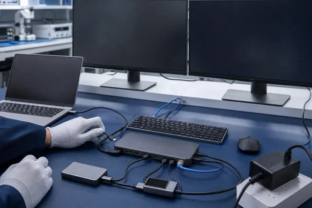
The combined test should therefore reproduce the busiest credible business case. For example, if a workstation is expected to run two displays, transfer a large file to external storage, use Ethernet, power a receiver, and charge the host, those functions belong in one test. The buyer should watch for:
- USB devices disappearing and re-enumerating;
- storage transfer errors or unexpected speed collapse;
- Ethernet link resets or sustained application failure;
- display flicker, blanking, mode fallback, or rearrangement;
- audio device changes;
- host charging warnings or battery decline beyond the accepted result;
- dock resets after plugging in a bus-powered peripheral;
- excessive temperature or protective shutdown, if temperature is part of the buyer’s requirement;
- functions failing after sleep, wake, restart, or power restoration.
Do not reduce this to one headline throughput figure. The purpose is to verify that the whole system remains usable under the named workload.
Display Validation: Record the Mode, Not Just “Video Works”
A visible picture is only the first check. Capture the active mode reported by the host and display. If the purchase requirement says two independent displays, a duplicated desktop is not a pass. If it requires a particular refresh rate, a silent fallback is not a pass. If the host’s internal screen must stay active, record that state too.
For every display test, record:
- host and port ID;
- dock and sample revision;
- display and input ID;
- cable or adapter on each output;
- desktop mode: extended, mirrored, or single display;
- active resolution and refresh rate on each display;
- color depth, HDR, and audio route only when required;
- whether the system was connected before or after boot;
- behavior after sleep, wake, restart, reconnect, and power restoration;
- any warning, fallback, manual recovery, or unsupported state.
Do not attribute failure automatically to the dock. The host may not expose the requested display route; the display input or cable may set a lower limit; an operating-system or firmware change may alter behavior. Repeat a failed case with one controlled variable changed at a time and retain both results.
Do not name a transport method that the supplier has not documented. This plan does not assume Thunderbolt, DisplayLink, MST, or another display technology. If a quoted device requires a proprietary driver or a particular alternate mode, the supplier must state that dependency, and the buyer must test the named host and software image.
PD Power Budget: Why “100 W Input” Is Not “100 W to the Host”
A dock’s advertised or listed power-input ceiling is not the same as power delivered to the host. USB Power Delivery involves a negotiated contract between participating components. The dock may consume power itself, provide power to downstream ports, and lose power in conversion. The power adapter, adapter-to-dock cable, dock design, upstream cable, host policy, host workload, and thermal state can all affect the observed result.
Use separate fields for:
P_source_rating: the adapter’s nameplate capability;P_dock_input_contract: the power contract observed at the dock input, where a suitable analyzer and procedure are available;P_dock_internal: dock electronics and conversion demand supplied or measured for the tested state;P_downstream: the simultaneous power used by attached downstream devices;P_margin: buyer-defined allowance for conversion loss, transient demand, and measurement uncertainty;P_host_port: power presented toward the host-facing connection, measured with suitable equipment where required;P_host_system_load: the host’s own changing workload;P_battery_change: observed battery charge or discharge behavior, which is not the same measurement asP_host_port.
For planning, not certification, the buyer can use:
Provisional host budget <= P_dock_input_contract - P_dock_internal - P_downstream - P_margin
This is a screening equation, not a USB PD rule and not a substitute for measurement. If any term is unknown, mark it unknown. Do not quietly set it to zero.
Hypothetical Planning Example
Assume a test instrument records a 90 W input contract for a candidate configuration. The supplier’s reviewed design data and the buyer’s simultaneous-load test together allocate 18 W to dock operation and downstream devices. The buyer reserves a further 7 W for conversion, transient, thermal, and measurement margin.
The provisional planning result is:
90 W - 18 W - 7 W = 65 W maximum provisional host budget
That calculation does not say the host receives 65 W. It says the configuration should not be approved on the assumption of more than 65 W without direct evidence. The buyer still records the host-facing contract or measurement and observes whether the selected host maintains, gains, or loses battery charge during the agreed workload.
Similarly, a dock marked “up to 100 W PD input” must never be recorded as “100 W charging to the laptop.” The 100 W statement may describe only an accepted input ceiling. The quote and sample report should separately state input requirements and the tested host-facing result.
Measure Under the Workload That Matters
Run the power observation in at least these states when they are relevant:
- dock connected with no downstream load;
- host idle with the required displays attached;
- full required peripheral combination active;
- host under the buyer’s representative CPU/GPU workload;
- after the dock reaches a stable operating temperature;
- after sleep/wake and dock-power restoration.
Record the adapter, both USB-C cables where removable, analyzer position, instrument model, firmware, sampling interval, and uncertainty. Do not use an unqualified inline meter as evidence for certification. Follow the equipment manufacturer’s safety and connection instructions.
Contextual next step: attach the completed power table to the custom cable and accessory RFQ checklist so suppliers quote against the same host-facing requirement rather than only an adapter-wattage headline.
Host Differences Must Remain Visible in the Approval
Create one result set per host model and per materially different port. Do not average incompatible systems into one statement.
A useful host matrix includes:
| Host ID | Exact port | OS / firmware | Required displays | Concurrent load | Power result | Decision |
|---|---|---|---|---|---|---|
| H1 | Port location recorded | Exact build recorded | Buyer-defined mode | Buyer-defined devices | Measured/observed | Pass / conditional / fail / not tested |
| H2 | Port location recorded | Exact build recorded | Buyer-defined mode | Buyer-defined devices | Measured/observed | Pass / conditional / fail / not tested |
| H3 | Port location recorded | Exact build recorded | Buyer-defined mode | Buyer-defined devices | Measured/observed | Pass / conditional / fail / not tested |
Use conditional pass only when the limitation is explicit and acceptable, such as a documented requirement to use one named host port, charger, cable, display input, or software build. A conditional pass must be reflected in product instructions, sales claims, and customer-support material. If the limitation cannot be communicated reliably, treat it as a release risk rather than hiding it in an engineering note.
Retest after a material change to the host image, dock firmware, controller, bill of materials, captive cable, power adapter, or packaging contents. Whether a change is material should be defined in the buyer-supplier agreement, not decided after a failure.
Minimum Approval Record
The final sample report should contain enough information for another qualified person to repeat the test:
- buyer project and test-plan revision;
- dock product code, sample ID, hardware revision, firmware, and date;
- supplier-stated port map and unresolved questions;
- host, port, operating-system, firmware, and driver identity;
- charger and every USB-C cable identity;
- display, peripheral, and test-media identity;
- required mode and actual result for every matrix row;
- power-source rating, negotiated values or measurements, instrument details, and host battery observation;
- test duration and reconnect or sleep/wake cycle count;
- screenshots, logs, photos, checksums, and failure evidence;
- deviations, workarounds, and untested combinations;
- decision: pass, conditional pass, fail, or not tested;
- approver, date, and reference to the retained sample or approved specification.
“Not tested” is an acceptable and important status. It is safer than converting missing evidence into an implied pass.
Risk Register for Sourcing and Private-Label Release
Risk 1: A maximum input number becomes a charging promise
Failure: marketing publishes “100 W laptop charging” because the dock page lists 100 W input.
Control: separate adapter capability, dock input, downstream allocation, host-facing result, and host battery behavior. Approve wording only for the tested configuration.
Risk 2: Ports pass individually but fail concurrently
Failure: video, Ethernet, and storage work alone but reset or fall back when used together.
Control: make the full intended combination a mandatory matrix row and retain logs for the entire duration.
Risk 3: A display count is copied across hosts
Failure: one laptop supports the requested arrangement, another similar-looking USB-C laptop does not.
Control: approve by exact host model, port, OS, firmware, and display mode. Link sales claims to the verified host matrix.
Risk 4: A silent display fallback is accepted
Failure: a picture appears, but resolution, refresh rate, color mode, audio route, or extended-desktop behavior differs from the requirement.
Control: capture the active mode for each display and repeat after boot, wake, and reconnect.
Risk 5: The tested cable or charger is not shipped
Failure: the approved sample uses one upstream cable or adapter, while production packaging contains another.
Control: place cable, adapter, label, and packing-list identities in the approved specification and change-control process.
Risk 6: A chipset, firmware, or bill-of-material change is invisible
Failure: production units enumerate or recover differently from the approved sample.
Control: require revision disclosure, supplier change notification, and defined revalidation triggers. Do not invent the controller identity; request it when it is commercially and technically necessary.
Risk 7: Certification language exceeds the evidence
Failure: a component document or logo is treated as proof that the finished dock is certified.
Control: match every declaration, report, listing, and logo claim to the exact product, applicant, model, revision, scope, and validity. Use the Cable Test and Compliance Documents Guide to structure that review.
Prepare the RFQ and Sample Request
Send a requirement that names the host, exact USB-C port, operating-system build, display arrangement, simultaneous peripherals, charger, upstream cable, expected host-power result, destination market, sample quantity, and intended order quantity.
Use these routes in sequence:
- Compare USB hub and dock listings.
- Prepare the controlled RFQ.
- Plan a model-specific sample.
- Send the completed compatibility matrix for quotation review.
The quote should identify confirmed details, supplier proposals, open questions, sample conditions, applicable documents, MOQ, packaging, and change-control assumptions. Final compatibility and commercial terms remain tied to the reviewed model and order.
Official Primary Sources
These sources support the system-level test method and terminology. They do not validate a CoreCavo catalog product.
- USB Implementers Forum — USB Type-C Cable and Connector Specification. The official specification landing page explains that USB Type-C defines a connector ecosystem with scalable power and performance; connector shape alone is not a complete product capability statement. https://www.usb.org/usb-type-cr-cable-and-connector-specification
- USB Implementers Forum — USB Power Delivery Specification. Use the current official revision and its applicable test specifications when a formal PD design or compliance review is required. https://www.usb.org/document-library/usb-power-delivery
- USB Implementers Forum — Cables and Connectors Compliance Resources. USB-IF lists different functional, cable, connector, and Power Delivery test documents depending on implemented capability. https://www.usb.org/cable_connector
- Microsoft Learn — USB Type-C Manual Interoperability Test Procedures. The official procedures include device enumeration, alternate-mode negotiation, charging, boot, power transitions, reconnect behavior, device topology, and stress or edge-case testing. https://learn.microsoft.com/en-us/windows-hardware/drivers/usbcon/type
- Microsoft Learn — Hardware Design of USB Type-C Systems. The official design overview shows the roles of Type-C/PD controllers, muxing, alternate modes, firmware, and operating-system integration. https://learn.microsoft.com/en-us/windows-hardware/drivers/usbcon/hardware-design-of-a-usb-type-c-system
- Apple Support — Connect Displays to Your Mac. Apple states that supported external-display count depends on the specific Mac model and on display resolution and refresh rate, supporting a model-specific rather than connector-only approval method. https://support.apple.com/en-us/102555
- VESA — DisplayPort Alternate Mode over USB Type-C. Use the VESA material to understand the standardized DisplayPort-over-USB-C route when it is actually declared for the host and dock; do not infer it from the connector. https://vesa.org/wp-content/uploads/2019/10/USB-DevDays-2019-VESA-DP-Alt-Mode-over-USB-Type-C.pdf
Sources, Methodology, and Responsibility
The method above combines official USB-IF specifications and compliance resources with official platform-vendor interoperability guidance. It is written as a buyer-controlled acceptance framework. A production test plan may require additional electrical, protocol, safety, environmental, regulatory, or software procedures defined by qualified personnel.
Catalog titles and attributes are reference inputs for model selection. They are not substituted for the supplier-confirmed specification, host matrix, measured sample result, applicable report, or production change record.