Choose a cable shield and its termination only after drawing four things separately: the signal conductors, the signal reference/return, the equipment chassis, and protective earth. Then identify the unwanted coupling mechanism and frequency range, the potential difference between endpoints, the connector/back-shell path, and the cable’s mechanical duty. A foil, braid or combination shield is not effective merely because it surrounds the conductors. Its continuity and end termination determine where intercepted current flows.
There is no safe universal answer to “ground the shield at one end or both ends.” One-end, both-end, capacitive or hybrid terminations solve different circuit and frequency problems. The correct choice is a system design decision governed by the interface, safety architecture, product standard, endpoint grounding, installation and verified EMC behavior. Never disconnect, lift, repurpose or route protective earth through a signal shield to cure noise. Protective-earthing work and any high-energy measurement must be performed only by qualified personnel under the applicable codes and equipment limits.
The buyer’s goal is not to buy “maximum shielding.” It is to give unwanted current a low-impedance path that does not become part of the wanted signal circuit, while preserving safety, mechanical life and manufacturability.
Begin with the four-layer reference map
Many failed cable specifications use one word—ground—for several electrically different nodes. Replace the word with a map.
1. Signal conductors
These carry the intended differential, single-ended, analog, digital, sensor, control or power-related signal. Record pair assignment, source/receiver topology, impedance and balance requirements where applicable. A differential pair is not automatically immune to interference; imbalance can convert common-mode energy into differential error.
2. Signal reference or return
This is the intentional circuit return or common used by the interface. It may be carried in a conductor, established locally at each isolated endpoint, coupled through a network, or defined by an interface standard. It should not be assumed identical to chassis.
3. Chassis or enclosure bond
Chassis provides a conductive equipment boundary and may receive a cable shield at the connector entry. A low-impedance, mechanically continuous connection at that boundary can be important at high frequency. Whether chassis is coupled to circuit common, and how, is an equipment-design question—not something the cable assembler should invent.
4. Protective earth
Protective earth is a safety function governed by the equipment and installation. It is not an optional noise-control wire. A cable drawing must not tell an operator to remove a protective bond because hum or communication errors occur. A qualified safety engineer must resolve any interaction among chassis, protective earth and cable shields.
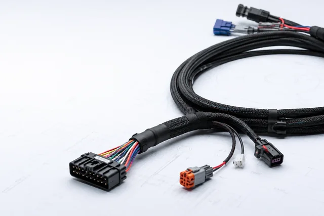
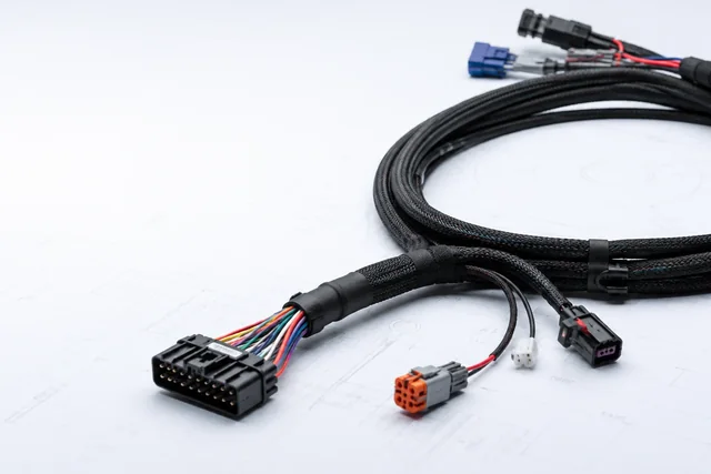
For each endpoint, draw where these four layers connect, remain isolated or couple through intentional components. Include connector shells, backshells, panel bonds, drain wires and pigtails. The drawing often reveals that “shield at both ends” actually means a drain wire to circuit common at one end and a shell-to-chassis bond at the other—two very different structures hidden by one phrase.
Identify how interference reaches the circuit
Shield selection should answer a coupling problem. Typical mechanisms include:
- capacitive or electric-field coupling, in which changing voltage couples through stray capacitance;
- inductive or magnetic-field coupling, in which changing current and loop area matter;
- radiated electromagnetic coupling, which becomes important as structures behave more like antennas;
- common-impedance coupling, in which wanted and unwanted currents share a non-zero impedance;
- common-mode conversion, where imbalance at a cable, connector or termination turns common-mode energy into differential error;
- cable-to-cable coupling, affected by route, separation, parallel run length and frequency;
- emissions from the intended signal, where the cable itself becomes part of the radiating structure.
Texas Instruments’ EMI/RFI board-design application report describes cables as possible radiated-emission antennas, susceptibility antennas and cable-to-cable coupling paths. Its Ethernet guidance also emphasizes connector/chassis transitions and common-mode balance. These are engineering mechanisms, not universal cable recipes. A recommendation written for a particular Ethernet PHY or connector should not be copied into an unrelated low-level sensor assembly.
Create a threat worksheet:
| Field | Buyer question |
|---|---|
| Wanted signal | What amplitude, bandwidth, edge rate, impedance and balance must be preserved? |
| Noise source | Motor drive, relay, switching supply, radio transmitter, ESD event, adjacent digital cable or the assembly’s own signal? |
| Coupling route | Electric field, magnetic field, common impedance, radiation or unknown pending test? |
| Frequency/time behavior | Continuous, switching harmonic, transient, burst or broadband? |
| Endpoint relationship | Same chassis, separate chassis, isolated circuits, uncertain earth potentials or moving equipment? |
| Installation | Length, separation, tray, bundle, enclosure entry, flex and connector access? |
| Failure criterion | Measurement error, bit errors, resets, radiated emissions, immunity class or safety concern? |
| Applicable rule | Product/interface/safety/EMC standard and test level/revision? |
If the coupling mechanism is unknown, preserve design options for prototypes rather than freezing a slogan into the drawing.
Match shield construction to the real duty
Foil shields
A foil shield can provide high coverage with low bulk. It is commonly paired with a drain wire because thin foil is not normally treated like a robust round conductor for termination. Its performance depends on foil material, overlap, drain contact, orientation, flex life and how the termination transitions into the connector. Repeated flexing can change a construction that performed well in a static sample.
Do not write only “100% foil coverage.” Ask how coverage is defined, how seams/overlap and bends behave, and how electrical continuity reaches the required termination. The drain wire is part of that answer, not a generic extra ground conductor.
Braid shields
A braid can offer robust circumferential contact and flex performance, but its coverage and impedance depend on strand material, carrier construction, braid angle, optical coverage, termination and frequency. More braid can add diameter, mass, stiffness and termination complexity. A drawing should state the controlled construction and acceptable termination, not rely on a photograph.
Foil plus braid
A combination can address complementary coverage, impedance and mechanical needs. It can also create more layers to terminate incorrectly. Specify whether layers are electrically common, isolated, cut back, folded, bonded to a ferrule or terminated separately—and why. “Double shield” is not a complete engineering definition.
Individually shielded pairs and overall shield
Individual pair shields can reduce internal coupling; an overall shield addresses interaction with the environment. The choice affects diameter, capacitance, flexibility, breakout design and termination. State whether each pair shield, drain and overall shield remains distinct at the connector. Accidental joining at a backshell can defeat the intended architecture.
Twist, balance and routing remain important
A shield does not replace pair balance, controlled geometry or sensible routing. Twisting reduces loop area and helps external fields couple more equally into a pair; receiver common-mode rejection then matters. Separation from noisy conductors and avoiding long parallel routes can reduce coupling before shield current becomes a problem. Validate the combined design.
The termination is part of the shield
At high frequency, a long drain-wire or pigtail connection adds inductance and can leave the enclosure entry electrically open even though a continuity meter reads near zero. A circumferential backshell or clamp may provide a lower-impedance high-frequency transition, but it must be compatible with the connector, enclosure and system architecture. At lower frequencies or in circuits with endpoint potential differences, a DC bond at both ends may allow unwanted shield current. These facts explain why termination cannot be selected from continuity alone.
Record these geometry details on the drawing:
- shield cutback length and permitted variation;
- drain-wire size, insulation and maximum exposed/pigtail length where used;
- ferrule, clamp or crimp method and controlled tooling;
- 360-degree termination requirement, if the system design calls for it;
- connector shell and backshell material/finish and electrical continuity path;
- shell-to-panel contact and coatings/gaskets that could interrupt it;
- unused shield/drain treatment and insulation from neighboring contacts;
- strain relief so mechanical load does not pull on the shield termination;
- corrosion/environmental compatibility of the material stack.
A cable assembler can reproduce a defined termination. The assembler should not decide whether a spare drain goes to signal common, chassis or nowhere when the schematic is ambiguous.
Why one-end versus both-end rules conflict
One-end shield termination is often used to avoid low-frequency circulating current when endpoints sit at different potentials. Both-end termination can provide a more complete high-frequency boundary when the chassis and bonding architecture are designed for it. A hybrid can block DC while coupling higher-frequency energy. Each has failure modes.
The correct reasoning asks:
- What frequency range must the shield control?
- Is the shield intended to intercept electric fields, contain common-mode current, or do both?
- What voltage may exist between endpoint chassis/earth systems?
- Are signal circuits isolated or referenced between endpoints?
- What does the interface/product standard prescribe?
- Does the connector support the intended termination with low, repeatable impedance?
- What happens during ESD, surge or a fault condition?
- How will the architecture be verified in the real equipment?
Analog Devices’ application material offers one-end and both-end examples for specific balanced/instrumentation or RS-485 contexts. Those examples are useful because they expose ground-potential and common-mode constraints; they must not be converted into a rule for all signals. A high-speed digital link crossing two chassis can require a different treatment from a microvolt sensor connected to an isolated amplifier.
If a product standard or safety analysis mandates a bond, follow it. Do not insert a capacitor, resistor, fuse or other component into a shield/safety path without system-level electrical, safety, transient and EMC review. A drawing copied from an application note is not a project approval.
Treat the connector and enclosure entry as one boundary
The shield should not arrive at a metal connector shell and then lose continuity through a painted panel, insulating washer or plastic backshell unless the design explicitly intends that break. Conversely, a metal shell bonded to chassis can defeat an intended isolated shield if the cable drawing ignores the equipment interface.
Request an endpoint boundary sketch for both ends:
cable shield → termination hardware → connector shell/selected pin → equipment receptacle → panel/chassis/reference network
List mating connector part numbers, panel finish, gasket/contact features and mounting method. Verify continuity/impedance using the approved method after final assembly, not only on an open bench backshell.
For hybrid assemblies with multiple shield zones, label each zone and its boundary. A shield over a noisy power section may need different routing from a low-level signal-pair shield. Breakout length and exposed unshielded conductors should be controlled because the last centimeters can dominate susceptibility or emissions.
Translate the architecture into a buildable specification
Once a qualified engineer approves the system concept, procurement needs reproducible fields:
- cable core: conductor count/size/material, pair assignment, impedance or balance requirement;
- shield layers: material, coverage/construction definition and drain association;
- layer separation: which shields are common or isolated;
- end A and end B: connector, pinout, shell and shield termination in explicit words;
- chassis/reference map: informative system diagram controlled by the design authority;
- cutback, pigtail, ferrule/clamp/crimp and strain-relief dimensions;
- environmental/flex/diameter constraints and minimum bend rule from the cable design;
- workmanship and inspection standard only when contractually applicable;
- electrical inspection and continuity/isolation test points;
- EMC or functional validation plan at assembly and system level;
- labeling, revision, approved materials/substitutions and change notification.
IPC/WHMA-A-620E is an industry workmanship/acceptability standard for cable and harness assemblies. NASA-STD-8739.4 is an active NASA workmanship standard for interconnecting cables/harnesses. Either can be relevant when a contract invokes it. Neither chooses the correct one-end/both-end grounding topology for every product, and neither should be claimed without reviewing the purchased standard, class/addenda and contract.
Three hypothetical decision cases
The following cases are hypothetical. They are not CoreCavo designs, tests, customers or performance claims.
Case A: low-level sensor beside a variable-frequency drive
A remote sensor carries a small balanced analog signal to an acquisition unit. Both equipment grounds and the isolation scheme are documented. The route runs near a motor drive cable. The team first reduces coupling with pair twist, separation and route control, then compares approved shield termination options using measured noise and the real endpoint potential conditions. It does not automatically bond both ends or disconnect protective earth. The released drawing records which end owns the shield connection and how the drain is insulated at the other end.
Case B: high-speed interface through two metal enclosures
A high-edge-rate differential interface exits one chassis and enters another. The EMC engineer treats connector shells, panel bonds and the overall shield as a continuous high-frequency boundary. The prototype preserves a circumferential termination option and minimizes unshielded breakout. Both-end chassis connection is evaluated together with common-mode current, equipment bonding and immunity/emissions evidence. A DC continuity result alone is not the release criterion.
Case C: moving harness with foil-only prototype
A static prototype passes an initial bench check, but the assembly will flex repeatedly in service. The team recognizes that foil/drain continuity, stiffness and strain at the termination may change. It evaluates a braid or combined construction against flex, diameter, mass and EMC needs, then repeats electrical and system validation after the approved mechanical conditioning. It does not market the new construction as “double shielded performance” without the applicable evidence.
Validate at three levels
Level 1: assembly identity and workmanship
Confirm materials, cable marking, shield layers, drain routing, cutback, termination hardware, shell continuity, pinout, strain relief and traceability against the controlled drawing. Use the invoked workmanship standard and class exactly. A cosmetic inspection cannot prove high-frequency termination performance.
Level 2: electrical assembly checks
Perform the approved continuity, isolation, resistance, bond or transfer-impedance-related measurements that the design requires. The method, test points, fixture, frequency, limit and uncertainty must be specified. A low-frequency ohmmeter result cannot be relabeled as broadband shielding effectiveness.
Any test involving hazardous voltage, protective bonding, energized enclosures, surge, high current or access to exposed conductors must be carried out by qualified personnel with suitably rated equipment, risk controls and the applicable device/standard limits.
Level 3: system EMC and functional evidence
Test the complete equipment and cable in the relevant configuration: endpoint chassis, power supplies, cable route/length, loads, operating modes and nearby noise sources. Use the applicable emissions/immunity standard and accredited laboratory where required. Monitor both formal EMC criteria and the real function—data errors, sensor offset, resets, control loss or thermal behavior.
A passing system test applies only to the documented configuration and change-control envelope. It does not automatically certify a standalone cable, every length or every enclosure.
Diagnose by current path, not by adding layers
| Symptom | First evidence to preserve | Controlled questions | Weak shortcut to avoid |
|---|---|---|---|
| Low-frequency hum or offset | Endpoint references, shield connections, power/earth state and measured potential | Is shield current sharing the signal path? Is isolation/reference implemented as designed? | Disconnect protective earth |
| Radiated emissions at a high-frequency band | Frequency, operating mode, connector/chassis geometry and common-mode current | Is the shield discontinuous at entry? Is a pigtail/breakout electrically long? Is pair balance poor? | Add thicker foil without locating the path |
| ESD causes reset | Discharge location, current path, chassis bond and signal/reference behavior | Is energy reaching circuit common through the cable/connector? Does the approved protection architecture work? | Change cable pinout during the test |
| One build passes; another fails | Material/termination/tooling/revision trace | Did cutback, braid coverage, plating, ferrule or shell contact change? | Average the two results |
| Continuity passes; EMC fails | Test frequency/method and complete termination geometry | Did the meter miss high-frequency impedance or enclosure discontinuity? | Declare the shield effective from resistance alone |
Freeze evidence and retest the right changes
The release package should contain the reference map, threat worksheet, approved schematic/drawing, cable/connector specifications, prototype identities, workmanship record, electrical data, EMC/system configuration, raw reports, deviations and signed disposition. Keep photographs that show the termination before it is hidden by overmold where the process permits and the record is controlled.
Review or retest when a change can alter shield impedance, balance, coupling, ground current, safety or mechanical life. Examples include foil/braid material or coverage, drain size/location, pair lay, cable length, connector shell/plating, backshell/clamp/ferrule, cutback/pigtail, overmold, panel finish, endpoint chassis network, isolation, power supply, cable route/bundle, flex duty or applicable standard revision.
The custom cable RFQ guide covers the broader set of electrical, mechanical, environmental and commercial input fields. The cable test and compliance documents guide explains how to bind evidence to the correct product and revision. The custom cable assembly page is the commercial destination; it should not inherit unverified shielding performance from this resource.
For an engineering review, send the signal/reference/chassis/protective-earth map, interface and endpoint drawings, threat/frequency information, route and flex duty, proposed shield/termination, applicable standards, validation plan, quantity and change-control needs through the CoreCavo RFQ page. A submission begins feasibility review; it does not confirm design safety, EMC compliance, certification, production capability, price or schedule until the exact proposal and evidence are approved.
Sources
| Source URL | Organization | Accessed | Scope used in this guide |
|---|---|---|---|
| https://webstore.iec.ch/en/publication/4234 | International Electrotechnical Commission (IEC) | 2026-08-12 | Official scope of IEC TR 61000-5-2:1997 for EMC-oriented earthing and cabling in installations; used as system guidance context, not as a free substitute for the purchased report or project standard |
| https://www.ti.com/lit/an/snla016b/snla016b.pdf | Texas Instruments | 2026-08-12 | Primary application report describing cable radiation/susceptibility/crosstalk and common-impedance mechanisms; used for engineering mechanisms, not a universal topology |
| https://www.ti.com/lit/an/snla107a/snla107a.pdf | Texas Instruments | 2026-08-12 | Primary Ethernet application report on imbalance, common-mode noise and connector/chassis coupling; applied only as a mechanism example |
| https://www.analog.com/media/en/technical-documentation/application-notes/441902615836055786153583156an273.pdf | Analog Devices | 2026-08-12 | Primary application note illustrating that grounding choice depends on circuit, frequency and ground-current context; not a universal one-end rule |
| https://www.analog.com/en/resources/analog-dialogue/articles/daq-umodule-application.html | Analog Devices | 2026-08-12 | Primary instrumentation application discussion of grounding/shielding and ground-loop risk; limited to illustrating system-reference analysis |
| https://www.electronics.org/news-release/ipc-releases-ipcwhma-620e-requirements-and-acceptance-cable-and-wire-harness | IPC International, Inc. DBA Global Electronics Association | 2026-08-12 | Official scope statement for IPC/WHMA-A-620E workmanship and acceptability; not a shield-topology selection rule |
| https://www.electronics.org/ipc-document-revision-table | IPC International, Inc. DBA Global Electronics Association | 2026-08-12 | Official standards revision table used to require revision control before contract use |
| https://standards.nasa.gov/standard/nasa/nasa-std-87394 | National Aeronautics and Space Administration (NASA) | 2026-08-12 | Official status/scope of NASA-STD-8739.4A Change 4 for NASA cable/harness workmanship; applicable only when contractually invoked |