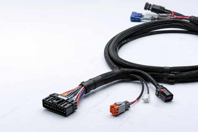
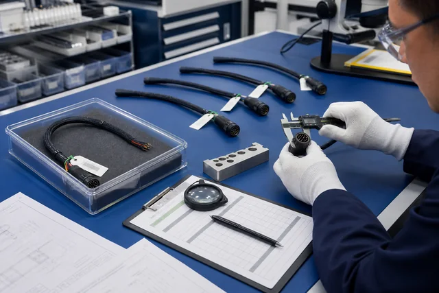
A strain relief is successful when normal pulling, bending and twisting are redirected into a controlled mechanical path before those loads concentrate at conductor terminations, contacts or a sharp cable exit. An overmold can form that path, but the presence of molded plastic does not prove adequate retention, flex life, sealing or material compatibility. Buyers should specify the movement, cable construction, connector constraints and evidence required, then approve the exact geometry, compound, process revision and test method as one design.
The useful question is not “Can you add a boot?” It is: where will the load travel when a user pulls the cable, bends it against an enclosure, twists it during installation or repeatedly moves it in service? The answer determines what the strain relief must grip, where stiffness should change, what connector features must remain unloaded and which tests can expose a weak transition.
IPC lists over-molding/potting, connectorization, securing and finished-assembly installation within the scope of IPC/WHMA-A-620 training, while IPC-D-620 addresses cable and harness design requirements. Those documents provide a project team with a recognized framework, but they do not select a universal boot length, rib pattern, compound or acceptance force for every product. The governing product standard, connector application specification and buyer-approved drawing remain essential.
Review the assembly as four mechanical zones
Treating the molded area as a single solid object hides the interfaces where failures usually begin. A clearer review divides the assembly into four zones.
Zone 1 — the free cable. Record the complete cable construction, not just nominal outer diameter. Jacket material and grade, jacket wall, fillers, braid or foil, conductor bundle, roundness, OD tolerance, temperature range and intended flexing all affect how the cable responds to clamping and molding. A nominal diameter without tolerance is not enough to design a repeatable grip.
Zone 2 — the controlled transition. This is the portion that changes the assembly from flexible cable to the stiffer connector body. Its length, wall profile, ribs or slots, exit direction and local clearances determine whether bending is distributed or concentrated. More material is not automatically better: a very stiff transition can merely move the hinge point to its outer edge.
Zone 3 — retention and encapsulation. Here the design transfers axial and torsional load. Retention may come from controlled compression, mechanical interlock, adhesion to an approved jacket, engagement with connector features, an inner mold, or a combination. The specification should identify the intended mechanism. “Overmolded” alone does not say what prevents pullout.
Zone 4 — connector and mating interface. The overmold must not distort a connector housing, shift contacts, obstruct latches, cover required markings, change the mating datum or give users a grip point that encourages pulling on a fragile feature. Mating/unmating forces and panel clearances must be reviewed with the final molded geometry, not only with a bare connector.
This four-zone model creates a practical drawing review. Every critical dimension or test can be tied to one zone and one expected failure. It also makes change control clearer: a new cable OD affects Zones 1–3; a connector-housing revision can affect Zones 3–4; a harder compound can shift the flex point in Zone 2 even when exterior dimensions remain unchanged.
Start from motion and misuse, not from a boot sketch
Before geometry is discussed, write a movement statement. It should describe who handles the cable, how often, in which directions and around what obstacles. A laboratory patch cable moved twice during installation has a different problem from a handheld lead that is wrapped after every use. A cable leaving the side of a wall-mounted device has a different bending plane from a vertical pendant cable.
Use a movement worksheet such as this:
| Input | Buyer question | Design consequence to review |
|---|---|---|
| Axial pull | Can the user pull on the cable to unplug or route it? What accidental snag is credible? | Retention mechanism, connector load isolation and pull-test setup |
| Repeated bend | Is movement occasional, repeated or continuous? About which axis? | Transition profile, cable construction, bend location and cycle test |
| Torsion | Will the cable be twisted during installation, coiling or equipment rotation? | Anti-rotation features, conductor lay and torsion test |
| Side load | Can furniture, an enclosure edge or a panel cutout push the cable sideways? | Exit angle, clearance, abrasion protection and fixture geometry |
| Temperature | Will the transition be cold, hot or thermally cycled while loaded? | Grade-specific stiffness, adhesion and conditioned testing |
| Fluids and cleaning | Which named oils, cleaners, sweat, water or processing fluids contact the assembly? | Exact material compatibility and sealing requirement |
| Mating behavior | Where will a user grip, and how is the connector released? | Molded grip, latch access and prohibited pull points |
“Flexible” should not be accepted as the motion statement. Flex frequency, bend plane, expected radius, duty cycle and environment need project definitions. When those values are unknown, they remain open engineering questions rather than being filled with a generic catalog claim.
Shape the stiffness transition deliberately
The transition geometry controls where curvature develops. A solid cylinder ending at a sharp shoulder may be visually neat but can create a concentrated hinge just beyond the mold. A tapered profile, segmented ribs or another engineered compliance pattern may distribute curvature, but the correct approach depends on the cable stiffness, material grade, wall thickness, movement direction and available envelope.
Review these geometry decisions on the drawing:
- Cable exit centerline and angle. Confirm that the installed route does not force an immediate bend against the mold edge or nearby enclosure.
- Supported length. Define how much jacket is controlled and where the intended flexible region begins. There is no universal ratio that fits every cable.
- Transition profile. Identify solid, tapered, ribbed, slotted or other regions and the design purpose of each.
- Minimum and maximum wall. Thin areas can fill or tear differently; heavy areas can cool and shrink differently. Values require a tool/process review.
- Parting line, gate and ejector evidence. These features can affect appearance, flash, local strength and cable alignment. Their permitted locations belong on the tool review.
- Keep-out zones. Protect latches, screw heads, keying, contact datums, sealing faces, mating depth and user grip surfaces.
- Cable OD range. A cavity or gripper arrangement qualified at one OD may not control another. Treat OD changes as design inputs, not purchasing substitutions.
- Marking and orientation. If arrows, port names or branding are molded or printed, lock their relationship to signal direction and connector keying.
Molex’s public insert-mold tooling overview identifies separate tooling functions including loading bars, cable gripper bars and the strain-relief cavity. That separation is useful to buyers because it shows why cable positioning and OD control affect molded geometry. It does not establish that a particular supplier owns those tools or has qualified a CoreCavo design.
Define what the overmold is expected to grip
A load path should reach a mechanically suitable cable layer. If the molded body bonds only to a smooth jacket surface, retention may depend heavily on grade-specific adhesion, surface preparation, contamination and molding conditions. If it locks around a feature or undercut, the feature must be dimensioned and must not damage shielding or conductors. If an inner mold locates terminations before an outer mold forms the final body, both materials and both process stages need revision control.
Ask the design owner to mark the intended retention path on a section view:
external cable load → jacket/interlock interface → molded body or clamp → connector structural feature → equipment interface
Then mark the protected electrical path separately:
conductor → termination → contact retention → mating contact
The two paths should not rely on the same fragile point. Pulling on the cable should not be resisted primarily by crimp wings, solder joints, individual conductors or contact lances unless the product design and governing specification explicitly establish that arrangement.
TE Connectivity’s backshell guidance describes cable clamps as a way to prevent load from reaching contacts, and one TE application specification gives connector-specific strain-relief positioning advice. Those examples demonstrate the principle that support must be designed around a named connector system. Their distances and forces must not be copied into an unrelated molded assembly.
Material names are the start of compatibility work
PVC, TPE, TPU and other family names cover many formulations. Hardness, modulus, low-temperature behavior, oil resistance, flame behavior, color system, shrinkage and adhesion can vary by grade. The cable jacket and the overmold compound should therefore be identified by controlled material specifications or approved equivalents, not by a family label alone.
For each proposed pair, request evidence for:
- adhesion or mechanical interlock under the actual process route;
- effect of molding temperature and pressure on the jacket, insulation, shield and connector;
- dimensional stability, shrinkage and cable centering;
- hardness and flex behavior across the declared temperature range;
- response to named fluids, UV or cleaning agents when applicable;
- color, surface, odor and marking requirements;
- flammability or other product-standard evidence only where the exact construction is evaluated;
- approved regrind, colorant and material-substitution policy, if any.
Do not turn a resin data sheet into a cable-assembly guarantee. A supplier’s property value usually describes a particular material grade and test specimen under stated conditions. The finished overmold includes geometry, interfaces, processing history and other components. A compatible-looking first sample is not proof of aging performance.
Overmolding does not automatically create a seal
A continuous molded exterior may reduce exposed gaps, but environmental sealing is a separate requirement. Water or dust can travel along a cable jacket interface, connector seam, conductor bundle or poorly filled region. Capillary paths and pressure changes may matter even when the outside appears closed.
If sealing is required, the buyer should name the target condition, applicable product test, mating state, cable orientation, pressure or immersion details, preconditioning and acceptable result. The test must cover the finished connector/cable construction. Avoid phrases such as “waterproof overmold” without an exact rating, method and report tied to the item.
The same boundary applies to electrical insulation, flame behavior and chemical resistance. Overmold material data can support material selection; it cannot replace finished-assembly evidence where the requirement applies to the complete construction.
Run design-for-manufacture review before cutting production tooling
A productive DFM review asks whether the proposed design can be loaded, located, molded, cooled, removed and inspected consistently without damaging the assembly. The review should produce decisions, not only a rendered image.
Input freeze
Freeze the connector and cable drawings, cable OD tolerance, pinout, termination method, shield treatment, material grades, exterior envelope, keying and marking orientation. Identify buyer-supplied components and permitted sources.
Tool concept review
Review cavity split, loading/locating features, gripper concept, gate approach, vents, cable exit, expected witness marks and replaceable inserts. If several cable ODs or connector variants share a tool, document exactly which inserts and process windows differ.
Process-risk review
List credible effects of heat, pressure and handling: jacket deformation, insulation movement, conductor displacement, connector distortion, flash in the mating area, incomplete fill, voids, sink, off-center cable, contamination and marking defects. This list becomes the basis for first-article inspection.
Prototype decision
Choose whether soft tooling, machined mockups, printed ergonomic models or production-intent tooling is needed. A visual model can confirm grip and clearance but cannot establish molded-material adhesion or cyclic life. Label prototype evidence by what it can and cannot prove.
Release conditions
Define who approves drawing, tool, material, appearance and mechanical evidence. Do not authorize a bulk build from a photograph of one molded sample.
Build validation around failure modes
Test names alone are insufficient. A retention or flex test needs fixture geometry, direction, rate or cycle, preconditioning, sample quantity, measurement method and pass/fail criteria. These values should come from the applicable product standard or buyer engineering requirement.
| Failure mode | Evidence to plan | Post-test examination |
|---|---|---|
| Cable pulls out or slips | Axial retention in stated direction and fixture | Cable displacement, mold cracking, jacket damage, electrical continuity and contact position |
| Conductors fatigue near exit | Repeated bend at defined angle/radius/load and temperature | Continuity monitoring, conductor resistance, jacket whitening/cracks and sectioning if justified |
| Assembly twists in mold | Torsion test with defined rotation and restraint | Connector orientation, shield/termination damage and electrical result |
| Mold cracks or separates | Conditioned bend/pull after thermal or fluid exposure | Interface separation, crack origin and dimensional change |
| Connector becomes hard to mate | Dimensional and mating check before/after molding and conditioning | Latch, mating depth, keying, seal face and contact alignment |
| Sealing path fails | Exact ingress method for the named product requirement | Entry location, interface condition and whether failure occurred mated or unmated |
Electrical continuity alone can miss a mechanically damaged but not yet open conductor. Appearance alone can miss contact movement. The approval record should combine mechanical observations, dimensions and relevant electrical checks.
NASA-STD-8739.4 is a high-reliability workmanship standard for NASA interconnecting cable and harness assemblies. It is useful as an example of disciplined cable/harness workmanship control, not as an automatic requirement or certification claim for a commercial cable. If a customer contract cites NASA, IPC or another standard, the exact revision, class/addendum and precedence must be resolved by qualified reviewers.
Read defects as information about the load path
When a sample fails, record where motion or fracture occurred rather than replacing it immediately.
- A jacket that slides inside an intact mold points toward inadequate grip, incompatible adhesion, contamination or OD/process variation.
- A cable that breaks exactly at the outer edge of a stiff boot points toward a concentrated bend transition or an unsuitable cable construction for the motion.
- Contact pushback after pull indicates that the mechanical path reached the termination system.
- Cracking along a knit line or thin feature may indicate geometry and processing interaction, not simply “bad material.”
- Flash near a latch or mating face indicates a tooling/control issue that can affect function even if the cable passes pull.
- A seal failure limited to one orientation may reveal an interface path or fixture/use condition that the original test did not represent.
The corrective action should change one controlled factor and preserve failed samples, photographs, measurements and revisions. Otherwise, the next sample may look better without explaining why.
Three hypothetical buyer decisions
The following scenarios are hypothetical. They are not CoreCavo test results, production capabilities or customer cases.
Handheld service lead
A technician repeatedly coils a short diagnostic lead and often pulls it sideways from the instrument. The team records repeated bend in two planes, occasional torsion and glove access to the connector latch. A long solid boot conflicts with the enclosure, so several transition concepts are compared. Approval requires latch access, cold-conditioned flex and continuity monitoring. The final geometry cannot be selected from the connector photograph alone.
Fixed equipment harness
A harness is routed once inside equipment and secured to a chassis. Its dominant risk is assembly handling and an accidental service pull, not continuous flex. The buyer prioritizes cable retention, clearance from a sheet-metal edge, defined support placement and connector contact protection. A continuous-flex claim would add little value; installation drawing and retention evidence matter more.
Washdown-area sensor lead
The request includes liquid exposure and cleaning chemicals. The buyer does not write “TPU waterproof.” Instead, it names the fluids, concentrations, exposure conditions, connector mating state and ingress requirement. Material compatibility and finished-assembly sealing are reviewed separately, followed by mechanical testing after conditioning.
Release a mechanical design package, not a cosmetic sample
The purchase and approval record should include:
- connector, terminal, cable and material identifiers with revisions;
- cable OD range and relevant construction details;
- overmold drawing with datums, transition geometry, keep-outs and marking orientation;
- section view showing intended load path and protected termination path;
- tool number/revision and variant inserts where controlled by the supplier;
- approved visual criteria, including permitted parting line, gate and witness marks;
- retention, flex, torsion, dimensional and environmental test methods as applicable;
- sample quantity, conditioning, acceptance limits and raw results;
- mating and electrical checks before and after mechanical testing;
- change-notification triggers for cable, connector, compound, colorant, tooling and process site;
- packaging/support requirements that prevent the strain relief being pre-bent in transit.
This package complements—not replaces—the broader sample approval and FAI process. The cable sample approval guide explains release governance, while this page defines the mechanical evidence that such a release may need.
Prepare a strain-relief design review request
Use the custom cable RFQ guide for the complete commercial and technical input set. For the mechanical portion, send the connector and cable drawings, cable OD tolerance, installed route, expected pull/bend/torsion, temperature and fluid conditions, enclosure clearances, required standards and proposed acceptance tests. A photo or existing sample can help explain the use case, but it does not replace controlled dimensions.
Submit those inputs through the custom cable configurator or request-quote page to begin a feasibility review. That review does not confirm tooling availability, material compatibility, sealing, test performance, certification, MOQ or schedule until the exact design and evidence are evaluated.
Sources
| Source URL | Organization | Accessed | Scope used in this guide |
|---|---|---|---|
| https://www.ipc.org/ipc-document-revision-table | IPC International | 2026-08-12 | Official revision record for IPC/WHMA-A-620E and IPC-D-620A; confirms document identities, not CoreCavo compliance |
| https://www.ipc.org/ipcwhma-620-endorsement-program | IPC International / WHMA | 2026-08-12 | Official scope topics including over-molding/potting, connectorization, strain relief, marking and securing |
| https://standards.nasa.gov/standard/nasa/nasa-std-87394 | NASA Office of Safety and Mission Assurance | 2026-08-12 | Active NASA-STD-8739.4A Change 4 identity and scope for interconnecting cable/harness workmanship; used as a bounded high-reliability reference |
| https://www.molex.com/en-us/blog/mold-tool-design-for-insert-molding | Molex | 2026-08-12 | First-party description of loading bars, gripper bars and strain-relief cavity in insert-mold tooling; no universal geometry inferred |
| https://www.molex.com/en-us/products/cable-assemblies/custom-cable-assembly-solutions | Molex | 2026-08-12 | First-party explanation that overmolded strain relief can reduce stress at the connector/jacket interface; no CoreCavo capability inferred |
| https://www.te.com/content/dam/te-com/documents/aerospace-defense-and-marine/aerospace/global/TE-Connectivity-BackshellsInSpace-Whitepaper-2022-Optimized-FINAL.pdf | TE Connectivity | 2026-08-12 | Connector-maker discussion of clamps/boots supporting cable and keeping pull from contacts; application-specific, not a universal standard |
| https://www.te.com/content/dam/te-com/documents/appliances/global/ampinnergy-connectors-application-specification.pdf | TE Connectivity | 2026-08-12 | Example connector application specification showing named bend/support guidance; explicitly not copied to unrelated assemblies |