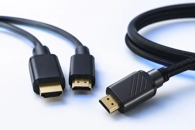
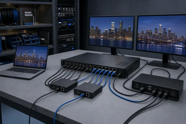
An HDMI fault should be investigated as a chain, not assigned immediately to “the cable.” First freeze the exact route and operating mode. Then classify the symptom: no image at all, brief dropouts, visible sparkles or corruption, an unexpected low-resolution fallback, loss after sleep or switching, or failure only with protected content. Test the simplest direct path at the same mode, change one component or setting at a time, and record each result. EDID/capability exchange, HDCP authentication, active-cable power and basic signal integrity are different layers; a successful test at one layer does not clear the others.
This method is for an installation or sample that already exists. It is not a guide to choosing between a splitter, switch, matrix or extender, and it does not decide whether a project should use one HDMI cable category rather than another. Those are separate procurement tasks. Here, the goal is to preserve enough evidence to identify the failing condition, return the route to a known state, and decide whether a component can be approved, contained or escalated.
Open an incident record before unplugging the route
The first instinct during a black screen is often to swap several cables, reboot every device and declare success when the picture returns. That may restore service, but it destroys the sequence that could explain the failure. Before changing the system—if operational and safety conditions permit—capture four things.
1. The route manifest
Draw every hop from source to display. Include the exact source output, adapters, wall plates, couplers, cables, extenders, switches, matrices, receivers, capture devices and display input. For each component, record model, revision, cable length, connector labels and power source. If an active or optical cable is directional, record which end is connected to the source.
Do not omit “simple” items. A short patch lead or female-to-female coupler can be the last changed variable. An AVR, KVM or matrix is not invisible merely because its switching function appears unrelated to video quality. The route manifest exists to prevent forgotten intermediaries from becoming uncontrolled assumptions.
2. The operating point
Record pixel dimensions, refresh rate, color depth and format where available, HDR state, audio route and whether compression is involved. Note whether the source is mirroring or extending another display. “4K” is not an operating point: 3840 × 2160 at 30 Hz and at 120 Hz place different demands on a path, and a fallback to a lower color or refresh mode can hide a marginal condition.
3. The symptom fingerprint
Describe what the user sees and when it begins. Useful details include:
- continuous or intermittent;
- appears immediately or only after warm-up;
- affects the entire frame or isolated pixels/lines;
- triggered by a particular application, protected program or display mode;
- follows sleep, input switching, hot-plug or a power interruption;
- recovers automatically, after reconnect, after restart or only after lowering the mode;
- occurs on one unit, one route, one batch or every installation.
Use a timestamped video or photograph when it captures the symptom accurately, but do not treat an image alone as a diagnosis.
4. The last known change
Record any replacement, firmware update, operating-system update, new display, changed mode, longer cable, new wall plate or altered power source. The last change is not automatically the cause, but it is a high-value comparison point.
Read the symptom as a test priority, not a verdict
Certain symptoms make some causes more worth testing, but none of the following observations proves a component defective on its own.
| Symptom | High-value first tests | Other layers still in scope |
|---|---|---|
| Stable desktop with isolated sparkles or short corruption | Repeat at the same mode on a short direct path; inspect seating and route; test a verified cable of equal capability | Endpoint output, receiver input, electrical noise, damaged connector, intermediary electronics |
| Full black screen from startup | Input selection, direction of active cable, auxiliary power, direct-path test, endpoint supported mode | EDID/capability exchange, HDCP, firmware, hardware failure |
| Image drops and recovers | Timestamp against power, temperature, movement and switching; inspect active-device power; simplify route | Marginal signal path, connector motion, thermal behavior, source/display reset |
| Lower mode works but required mode fails | Freeze both mode records; test direct path; verify every component’s documented limit | Source output and display input capability, link length, active device and cable |
| Desktop works but protected playback fails | Record content/application and HDCP requirement; isolate repeaters and converters | Source policy, receiver/repeater capability, authentication, firmware |
| Failure after sleep or input change | Reproduce the state sequence; capture active mode before/after; test direct path | EDID retention, hot-plug handling, power sequencing, driver/firmware |
The useful question is not “Which symptom belongs to which defective part?” It is “Which controlled test will separate the likely layers with the least disturbance?”
Establish a direct-path baseline
Where the deployment permits, connect the source directly to the display with a short, known and appropriately documented cable. Keep the source output and display input as close as possible to the failed operating point. Remove one intermediary at a time rather than replacing the whole route.
A direct path can produce three useful outcomes:
- The symptom remains. Focus next on the endpoints, their settings and the direct interconnect. Do not clear an endpoint merely because it works elsewhere at a different mode.
- The symptom disappears. One of the removed components, extra connections, power paths or route conditions remains suspect. Restore them one at a time.
- The operating point changes. The direct connection may have changed EDID, color mode, refresh rate, HDR or content-protection behavior. The apparent success is not comparable until the active mode is confirmed.
“Known-good” needs a definition. A cable that worked at 1080p on another display is not necessarily a valid reference for the required high-bandwidth mode. A switch that passes an unprotected desktop is not a known-good HDCP repeater for the target program. Record why each reference is considered valid and under what conditions.
Separate physical integrity from capability exchange
HDMI systems exchange information that helps the source understand the connected display and select an output. EDID is part of that capability-identification context. An intermediary may pass, store, combine or present display information according to its design. A changed EDID path can therefore alter resolution, refresh rate, color or audio choices even when the physical cable has not changed.
Ask the following questions:
- Does the source detect a display on the expected port?
- What display identity and supported modes does the source report?
- Does the active mode match the requirement or has it silently fallen back?
- Does a direct connection present different capabilities from the full route?
- Does an intermediary have an EDID mode, copy function, emulator or management setting?
- Did input switching, power loss or firmware change the information presented to the source?
Do not edit EDID, install an override or force an unsupported mode merely to make the picture appear. Preserve the original record first. An override can be a controlled diagnostic tool in qualified hands, but it can also hide the actual mismatch and create a configuration that the display cannot reliably accept.
When an image appears only after reconnecting, repeat a defined sequence: all devices off, power applied in the documented order, source restart, display input switch, cable reconnect and wake from sleep. Record which event changes detection or mode selection. The objective is a reproducible state transition, not a collection of random restarts.
Treat HDCP as an end-to-end authentication problem
HDCP concerns protected audiovisual content and defines roles for transmitters, receivers and repeaters. A source may display an operating-system desktop while protected playback fails because the second activity tests a different requirement. That pattern does not prove the HDMI cable itself “does not support HDCP.” Passive cable marketing should not replace device-level and route-level analysis.
For an HDCP-specific investigation, record:
- exact source model, output and firmware;
- content application, asset and required protection behavior;
- every receiver, repeater, switch, splitter, converter or capture device in the path;
- display model and input;
- whether direct source-to-display protected playback succeeds;
- whether the result changes after a particular repeater is restored;
- any error code or support log permitted by the equipment.
Do not use prohibited circumvention as a troubleshooting method. If a licensed device or managed platform reports an authentication limitation, escalate through its manufacturer or system owner. This article does not advise defeating content protection and does not claim that any CoreCavo product is HDCP compliant.
Active HDMI cables and AOCs add direction and power
An active HDMI cable may contain electronics in one or both connector heads. Optical and other active assemblies are commonly directional. HDMI LA’s Cable Power guidance states that active cable ends are labeled for source and sink and that reversed connection will not operate. Cable Power also requires support from both the cable and source for that powered route; products may provide a separate power connector for use when source support is absent.
Troubleshooting should therefore add four checks that do not apply in the same way to every passive cable:
- Are the Source and Display ends connected correctly?
- Does the exact cable require or offer auxiliary power?
- Is the approved power source present during cold start, sleep and recovery?
- Have bend, pulling, crushing or connector-head conditions changed since installation?
If an installed AOC fails after a pull, preserve pre-installation and post-installation records and follow an installation-specific method. Do not repeatedly flex or re-pull the assembly in a way that destroys evidence. The separate AOC installation acceptance guide addresses route controls and handover.
Use mode reduction as a diagnostic branch, not the repair
Lowering resolution or refresh rate can help determine whether the failure is associated with a more demanding operating point. It does not, by itself, identify which component is responsible. The source may change several variables at once: pixel rate, color format, color depth, HDR state or compression. Record the complete “failed” and “working” modes before drawing a conclusion.
Suppose the required mode fails while a lower mode is stable. The next sequence could be:
- reproduce both outcomes on the unchanged full route;
- reproduce both on the simplified direct route;
- confirm the display accepts the required mode on the same input using an appropriate reference source;
- confirm the source generates the required mode using an appropriate reference display or approved instrumentation;
- replace one interconnect or intermediary while holding mode and endpoints constant;
- restore the route one component at a time.
This sequence separates endpoint capability from route sensitivity. It also prevents a “solution” in which the system quietly remains at a lower mode than the contract requires.
Intermittent faults need a timeline
Dropouts are difficult because the system often works while the investigator is present. A timeline converts them into measurable events. Record:
- wall-clock time and elapsed time since power-on;
- active mode at the event;
- source/display/intermediary temperature or enclosure condition where safely and appropriately available;
- cable movement, connector touch or equipment vibration;
- nearby equipment switching or power events;
- application/content transition;
- audio behavior during the video event;
- whether the link recovers, renegotiates or stays absent;
- any device log or status indicator.
Do not claim electromagnetic interference, overheating or connector failure from timing correlation alone. Use the timeline to choose the next controlled test. For example, if every dropout follows an intermediary power event, repeat that event on the direct path and then with the intermediary restored. If movement at one connector reproduces the fault, take the route out of service as required and inspect it rather than repeatedly stressing it in normal operation.
A four-pass isolation protocol
The following protocol gives purchasing and engineering teams a common language.
Pass 1: Identity and configuration
Verify route manifest, component models, cable direction, power, source output, display input and active mode. Resolve mislabeled or undocumented configurations before performance testing.
Pass 2: Functional layers
Test unprotected desktop/video, audio, required operating mode and protected playback separately. A pass in one row must not be copied into another.
Pass 3: State transitions
Test cold boot, restart, input switching, hot-plug where permitted, sleep/wake and power restoration. Record automatic and manual recovery.
Pass 4: Controlled substitutions
Change one cable, intermediary, port, source or display at a time using an appropriate reference. Preserve the same mode and test stimulus. Record the exact before/after route.
At the end of each pass, choose one outcome: proceed to the next test, contain the suspect item, return to supplier/manufacturer evidence, or escalate to the endpoint/system owner. “Could not reproduce” is a valid status only when the test duration and conditions are recorded.
Two hypothetical examples
These examples are hypothetical. They are not customer cases, CoreCavo test results or product promises.
Example 1: Sparkles after a conference-room upgrade
The route includes a source, short patch cable, wall plate, long in-wall cable, receiver and display. The previous display used a lower operating mode. The team records sparkles only at the new required mode. A direct short cable is stable at that same mode, so the endpoints are not yet cleared, but the installed route becomes the next investigation area. The team restores the wall plate, long cable and receiver one at a time, records the first recurrence and retains the failed configuration. It does not declare the longest cable defective merely because it is longest.
Example 2: Black screen only for protected playback
The desktop and unprotected presentation are stable through a switch. Protected playback fails with an authentication message. Direct source-to-display playback succeeds. The team records the exact content and restores the switch with no other change. The failure returns, so the switch/repeater capability and configuration are escalated. Replacing passive cables at random would not address the layer separated by this test.
Define release criteria before closing the incident
A route should not be released because the image happened to return. The closure record should state:
- exact approved route and component revisions;
- required operating modes and active results;
- audio and protected-content scope, including anything not required or not tested;
- power and direction requirements for active components;
- state-transition tests and recovery behavior;
- test duration for intermittent conditions;
- substitutions made and evidence retained;
- unresolved limitations and ownership;
- change triggers that require re-test.
If a component is replaced, identify whether the replacement is a temporary containment or the new controlled baseline. If an EDID setting, firmware version or power adapter is essential, include it in the approved configuration. A repair that depends on undocumented state is not a durable release.
Know when to stop local troubleshooting
Stop and escalate when the route involves electrical safety concerns, damaged mains-powered equipment, inaccessible installed cable, prohibited content-protection workarounds, equipment under warranty, regulated systems or tests that require specialized instrumentation and competence. Follow the site owner’s safety procedure and the manufacturers’ instructions. Do not open active connector heads or modify installed wiring to satisfy this general guide.
Escalation should include the route manifest, symptom fingerprint, mode record and substitution log. That packet is more useful to a supplier or endpoint manufacturer than “HDMI keeps dropping,” and it reduces the risk of repeating destructive or inconclusive tests.
Submit the route, symptom and controlled evidence
Use the HDMI cable category only to identify a possible cable family, and the AV distribution category only when an intermediary is part of the recorded route. For feature/cable-category procurement, use the separate HDMI 2.1 vs 2.0 guide. For deciding whether the system needs a splitter, switch, matrix, extender or KVM, use the AV topology guide.
For a project-specific review, submit the route diagram, component models and revisions, cable types/lengths, active mode, symptom timeline, EDID/HDCP observations, power arrangement and controlled test results through the CoreCavo RFQ page. A review request does not establish the cause, guarantee compatibility or certify any component. Final findings depend on the exact products, endpoint evidence and reproducible test conditions.
Sources
| Source URL | Organization | Accessed | Scope used in this guide |
|---|---|---|---|
| https://www.hdmi.org/resource/cables | HDMI Licensing Administrator, Inc. | 2026-08-12 | Official HDMI cable category/certification context; exact current page path must be rechecked before publication if redirected |
| https://www.hdmi.org/spec21sub/ultrahighspeedcable | HDMI Licensing Administrator, Inc. | 2026-08-12 | Official model/length certification and labeling context for Ultra High Speed HDMI Cables; not evidence for any CoreCavo item |
| https://www.hdmi.org/spec2sub/cablepower | HDMI Licensing Administrator, Inc. | 2026-08-12 | Official Cable Power, active-cable direction, source support and auxiliary-power context |
| https://vesa.org/featured-articles/vesa-rolls-out-displayid-version-2-0-standard-to-optimize-plug-and-play-connectivity-for-leading-edge-displays/ | Video Electronics Standards Association (VESA) | 2026-08-12 | Official EDID/DisplayID capability-identification context; no model-specific diagnosis inferred |
| https://vesa.org/vesa-standards/ | VESA | 2026-08-12 | Official location listing EDID-related standards and implementation resources |
| https://www.digital-cp.com/about_dcp | Digital Content Protection LLC | 2026-08-12 | Official HDCP transmitter/receiver/repeater terminology |
| https://www.digital-cp.com/faqs | Digital Content Protection LLC | 2026-08-12 | Official HDCP repeater and licensed-system context; used to prevent cable-only HDCP conclusions |
| https://www.digital-cp.com/sites/default/files/specifications/HDCP%20on%20HDMI%20Specification%20Rev2_3.pdf | Digital Content Protection LLC | 2026-08-12 | Official HDMI mapping for HDCP Revision 2.3; scope limited to role/authentication context and not reproduced as implementation advice |